👋 Introduction
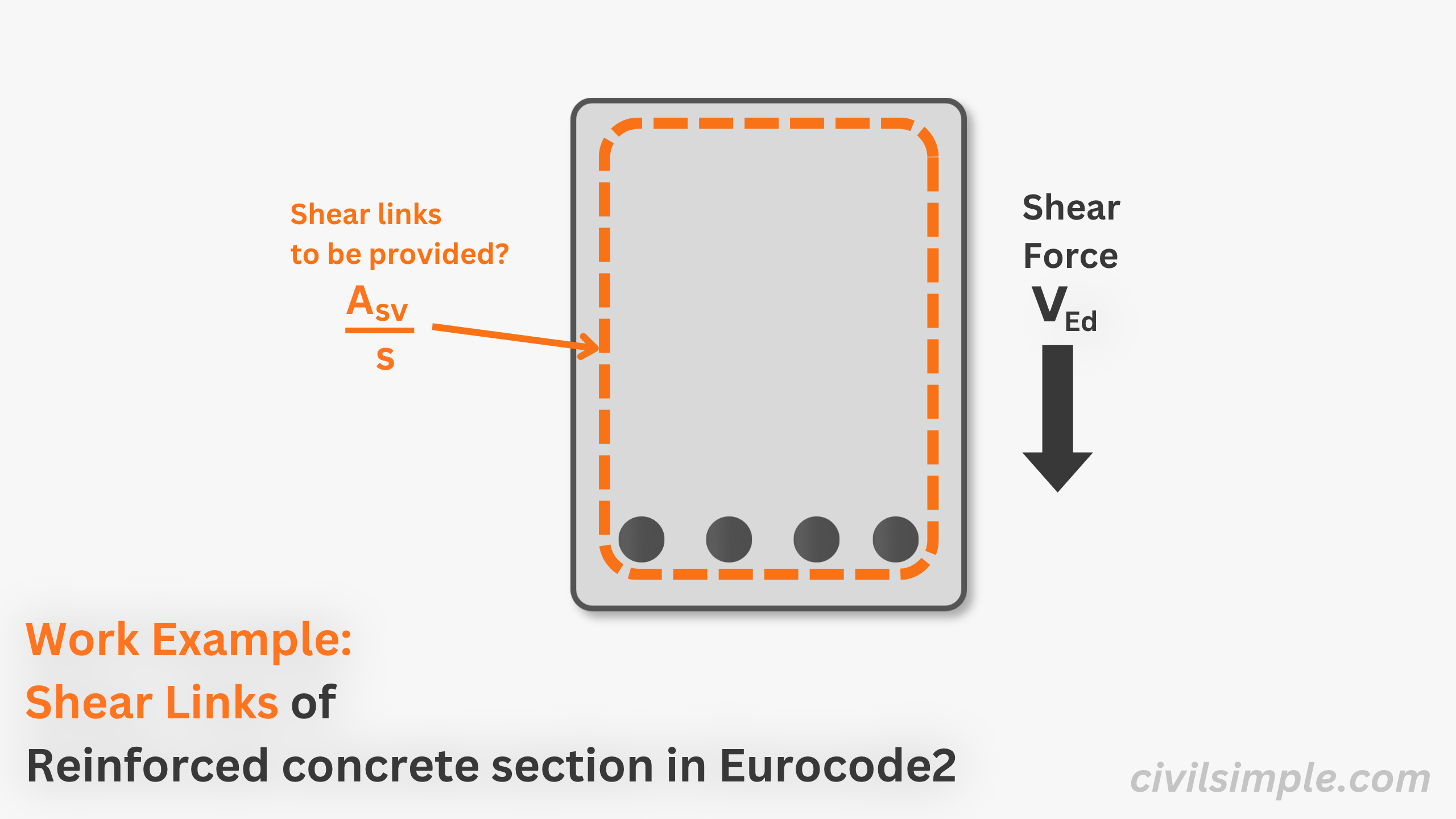
Shear design is one of the essential check in reinforced concrete beam design, as shear force existed in most situation. This article aims to demonstrate the steps involved in calculating the shear links to be provided of a section with given shear force through worked numerical examples.
📐 Design Data
Below are the design information of the shear analysis of the section.
| Geometry | ||
|---|---|---|
| Section | ||
| Width | 400mm | |
| Height | 600mm | |
| Reinforcement | ||
| Tension Area | 1470 mm² |
| Design Action | ||
|---|---|---|
| Shear Fy | 500kN |
| Material | ||
|---|---|---|
| Concrete | ||
| Strength | 30 MPa | |
| Rebar | ||
| Strength | 500 MPa |
| Assumption | ||
| = | ||
| = | ||
| = | ||
🔢 Calculation Steps
1. Determine concrete shear resistance without shear reinforcement
1.1Formula to be used
| From Cl 6.2.2(1), | ||
| = | ||
1.2Compute required parameters
| Effective Depth | ||
|---|---|---|
| = | ||
| = | ||
| = | ||
| Depth factor(Cl.6.2.2(1)) | ||
|---|---|---|
| = | ||
| = | ||
| = | ||
| Reinforcement Ratio(Eq. 6.6N) | ||
|---|---|---|
| = | ||
| = | ||
| = | ||
| Concrete Factor(N.A. Cl.6.2.2(1)) | ||
|---|---|---|
| = | ||
| = | ||
| = | ||
| Minimum Shear Resistance(Eq. 6.3N) | ||
|---|---|---|
| = | ||
| = | ||
| = | ||
1.3Compute Concrete Shear Resistance
| Concrete Shear Resistance(Eq. 6.2a) | ||
|---|---|---|
| = | ||
| = | ||
| = | ||
1.4Check against provided shear force
| Check Concrete Shear Resistance | ||
| < | ||
| < | ||
∴ Solely concrete shear resistance is not sufficient, shear links are required.
2. Determine compression strut angle
2.1Formula for compression strut angle
| To find V_{Rd,max},consider | ||
| = | ||
| = | ||
| = | ||
2.2Compute required parameters
| Strength Reduction Factor of Concrete(Eq. 6.6N) | ||
|---|---|---|
| = | ||
| = | ||
| = | ||
2.3Compute compression strut angle
| Inclined angle of compression strut | ||
|---|---|---|
| = | ||
| = | ||
| = | ||
3. Calculate shear links
3.1Calculate minimum shear links
| Min. Shear Rebar req.(Eq. 9.4 & 9.5N) | ||
|---|---|---|
| = | ||
| = | ||
| = | ||
3.2Determine required shear links
| Shear Reinforcement required(Eq. 6.8) | ||
|---|---|---|
| = | ||
| = | ||
| = | ||
3.3Calculate maximum shear links spacing
| Max. spacing(Eq. 9.7) | ||
|---|---|---|
| = | ||
| = | ||
| = | ||
Suggested Shear Rebars Arrangement
| Bar Dia. | nos. of legs | spacing | As/s(mm2/m) | notation |
|---|---|---|---|---|
| 8 | 2 | 100 | 1.00 | R8@100 2 legs |
| 12 | 2 | 200 | 1.13 | R12@100 2 legs |
| 16 | 2 | 200 | 2.01 | R16@100 2 legs |
∴ The Minimum Shear Rebar Area is 0.84 mm2/m and suggested shaer rebar arrangement is R8@100 2legs.
📄 Need a Full Design Check Report?
If you want similiar calculation analysis with your own design data, feel free to try our application, what you need is just the design data value, and a ready-to-submit design PDF report will be generated in a minute.

CivilSimple Team
The CivilSimple Team writes practical engineering guides for the profession and the curious. All articles are reviewed for technical accuracy before publication.