STRUCTURAL
-
 glossary
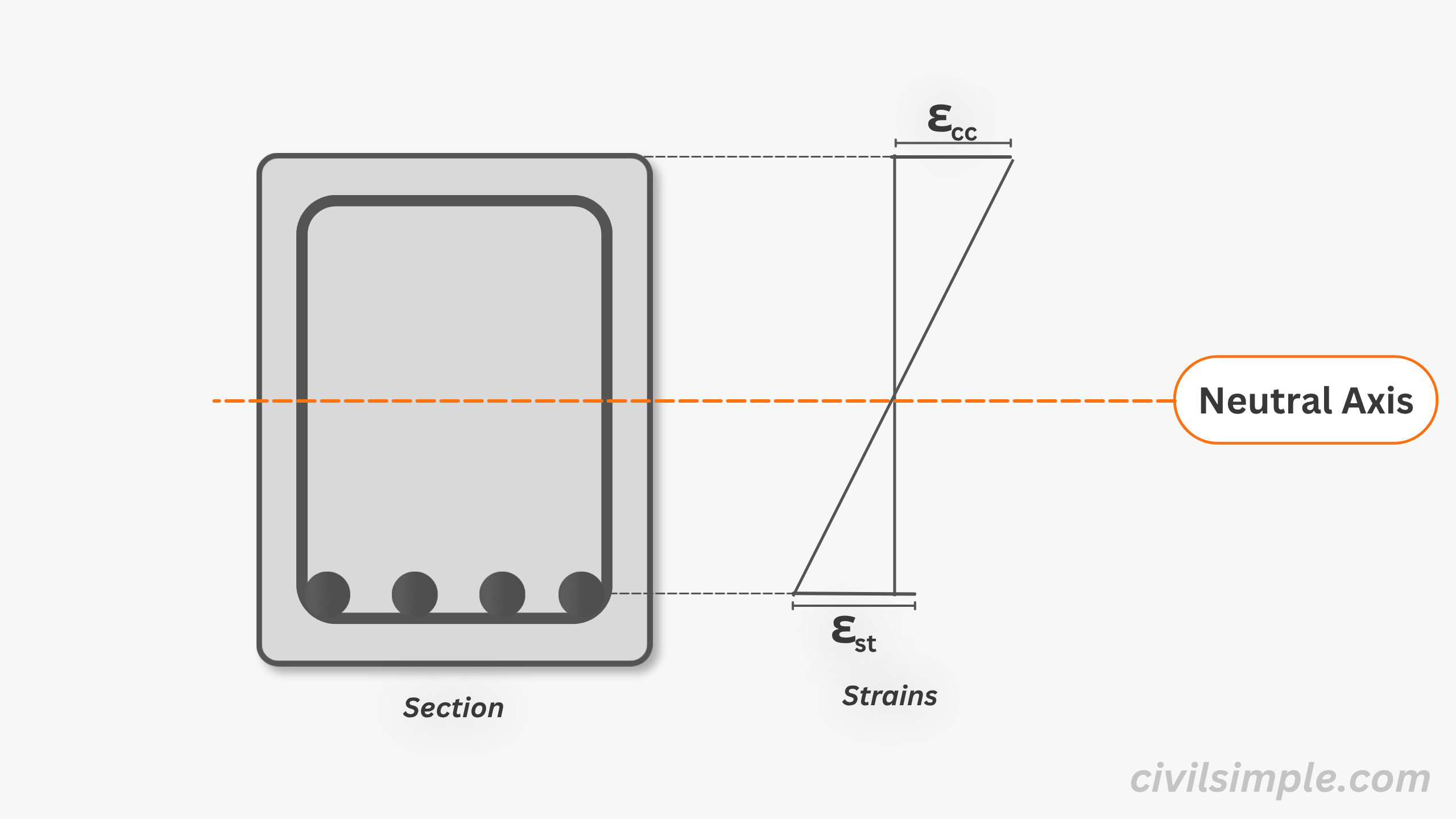
What is neutral axis?
Neutral axis is an imaginary line in a reinforced concrete section where longitudinal strain is zero. It separates the compression and tension zones, and its position depends on loading, material properties, and section geometry.
-
 glossary
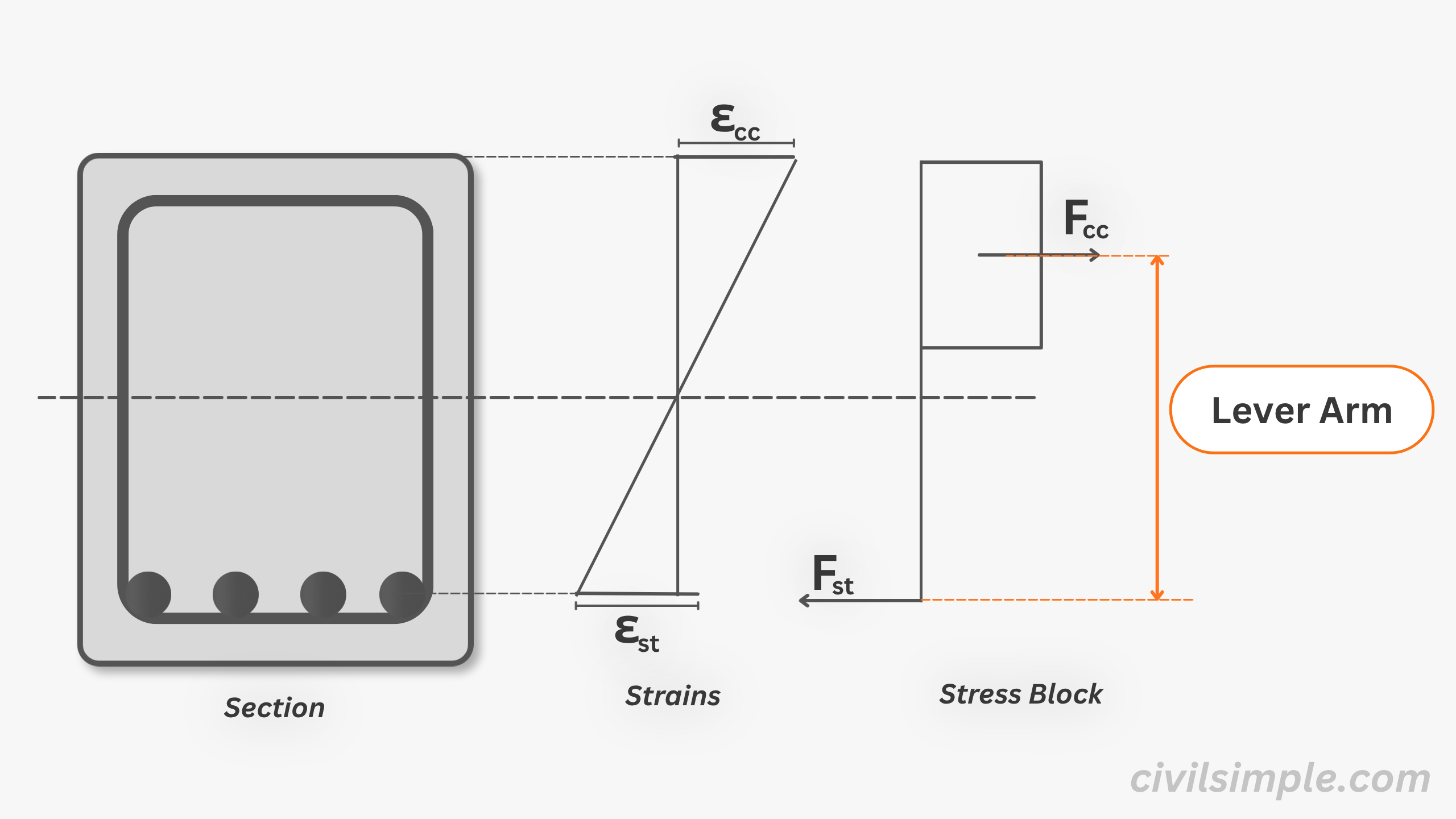
What is lever arm?
The lever arm is the distance between the centre of the compression force and the centre of the tension force acting on a section. It is a key parameter in moment capacity calculations. Understanding the strain distribution and stress–strain behaviour of concrete and steel is essential for determining the lever arm.
-
 glossary
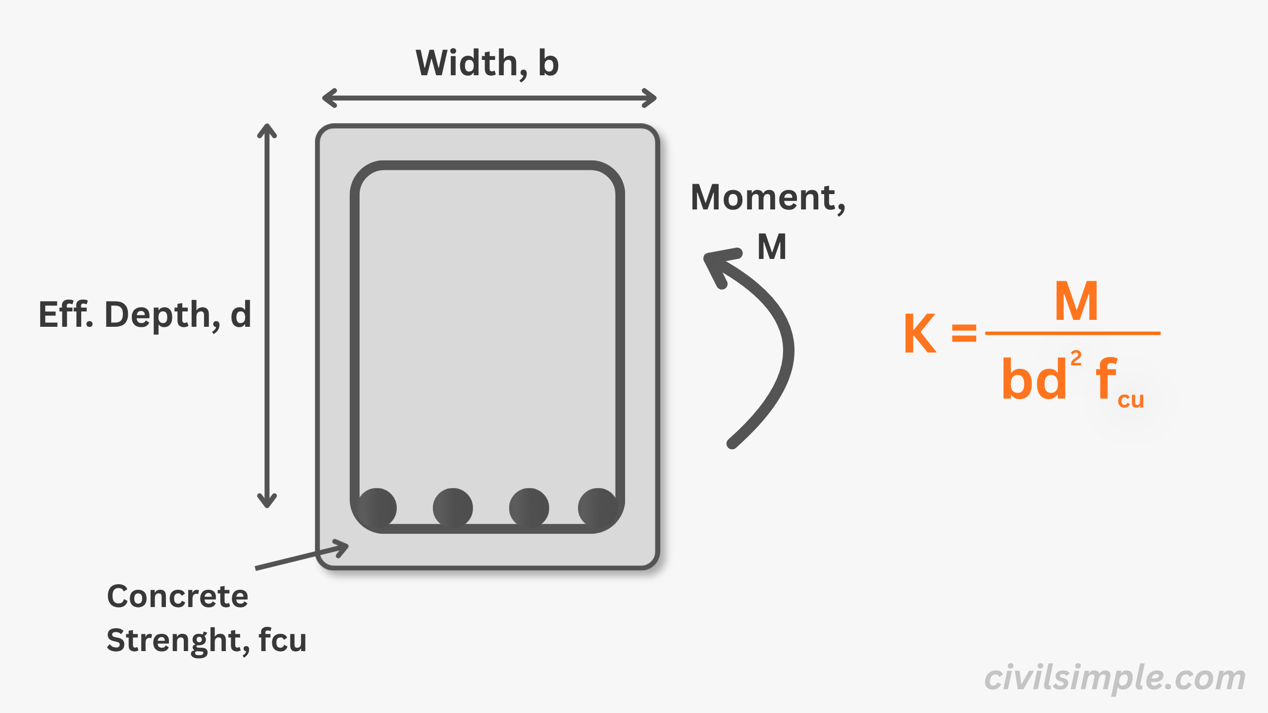
What is K coefficient?
K is a unitless coefficent defined as M/(fck • b•d²). It represents the ratio of design moment to section capacity parameters (width, effective depth, and concrete strength). It helps quickly assess whether a section satisfies code requirements, including ductility and compression zone adequacy, and provides a convenient way to determine the lever arm ratio (z/d) and hence the required tension reinforcement.
-
 assumptions
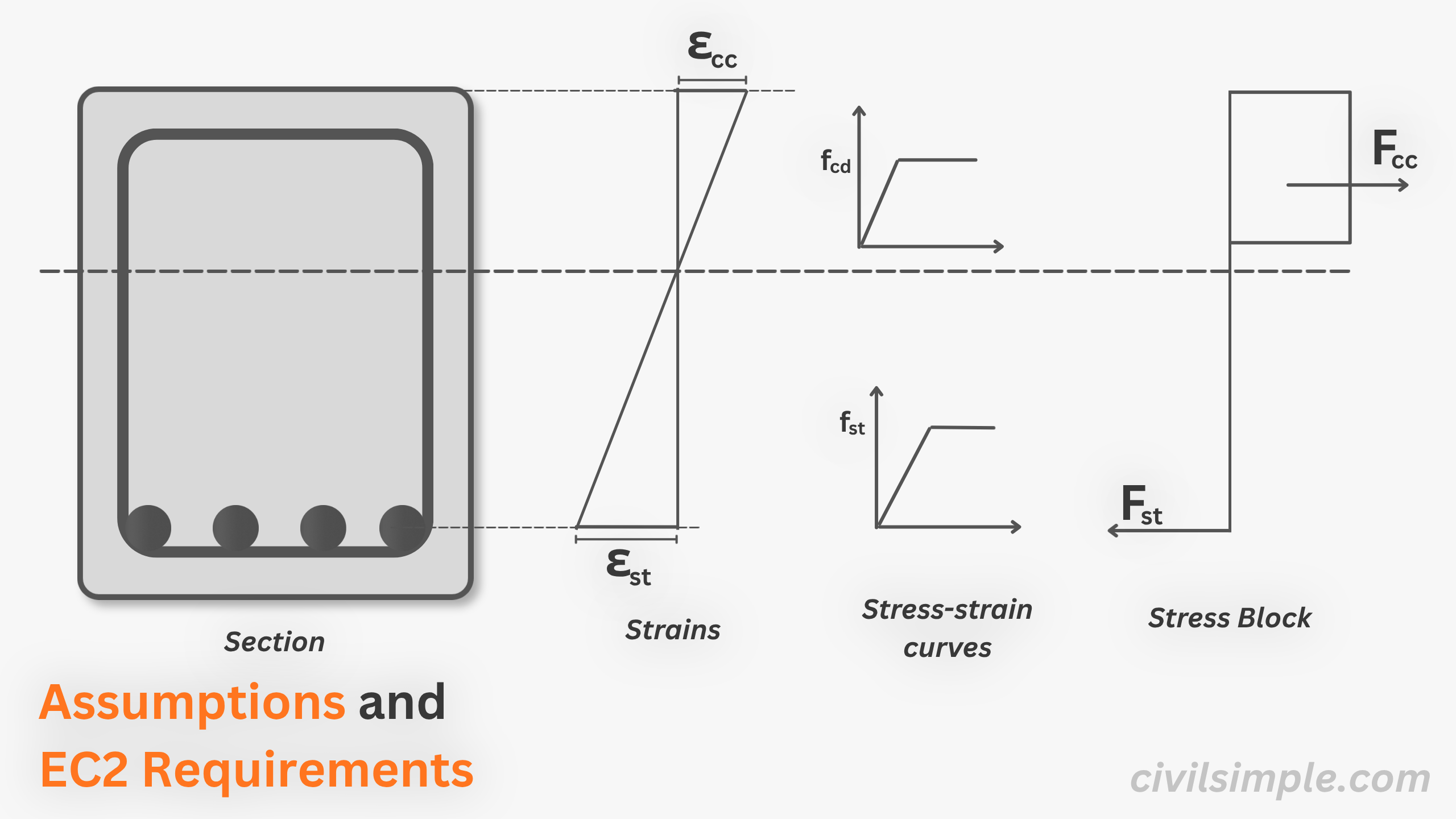
EC2 Bending Design - 6 Fundamental Assumptions and 3 Limitation
Learn the six key assumptions used in Eurocode 2 (EC2) bending design for reinforced concrete beams and slabs, including strain distribution, the stress block, force equilibrium, and ductility requirements.
-
 proof
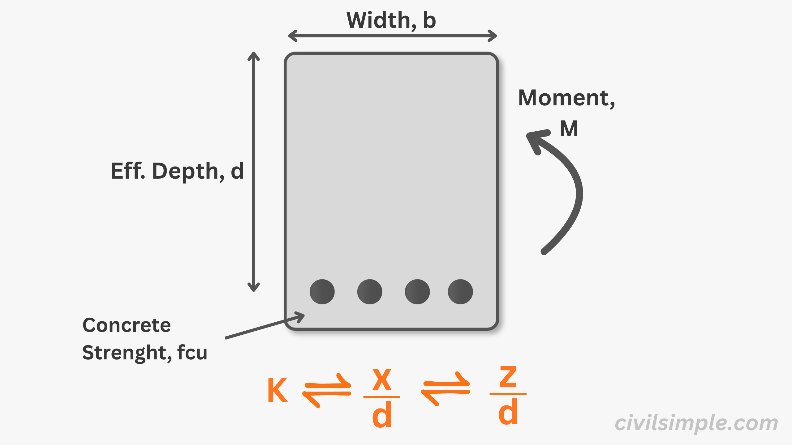
proofEC2 Bending Design - Derivation and Limits of x/d, z/d and K
Understand the relationship between x/d, z/d and K in EC2 bending design. Learn how these equations are derived and why their limits are important.
-
 work-example
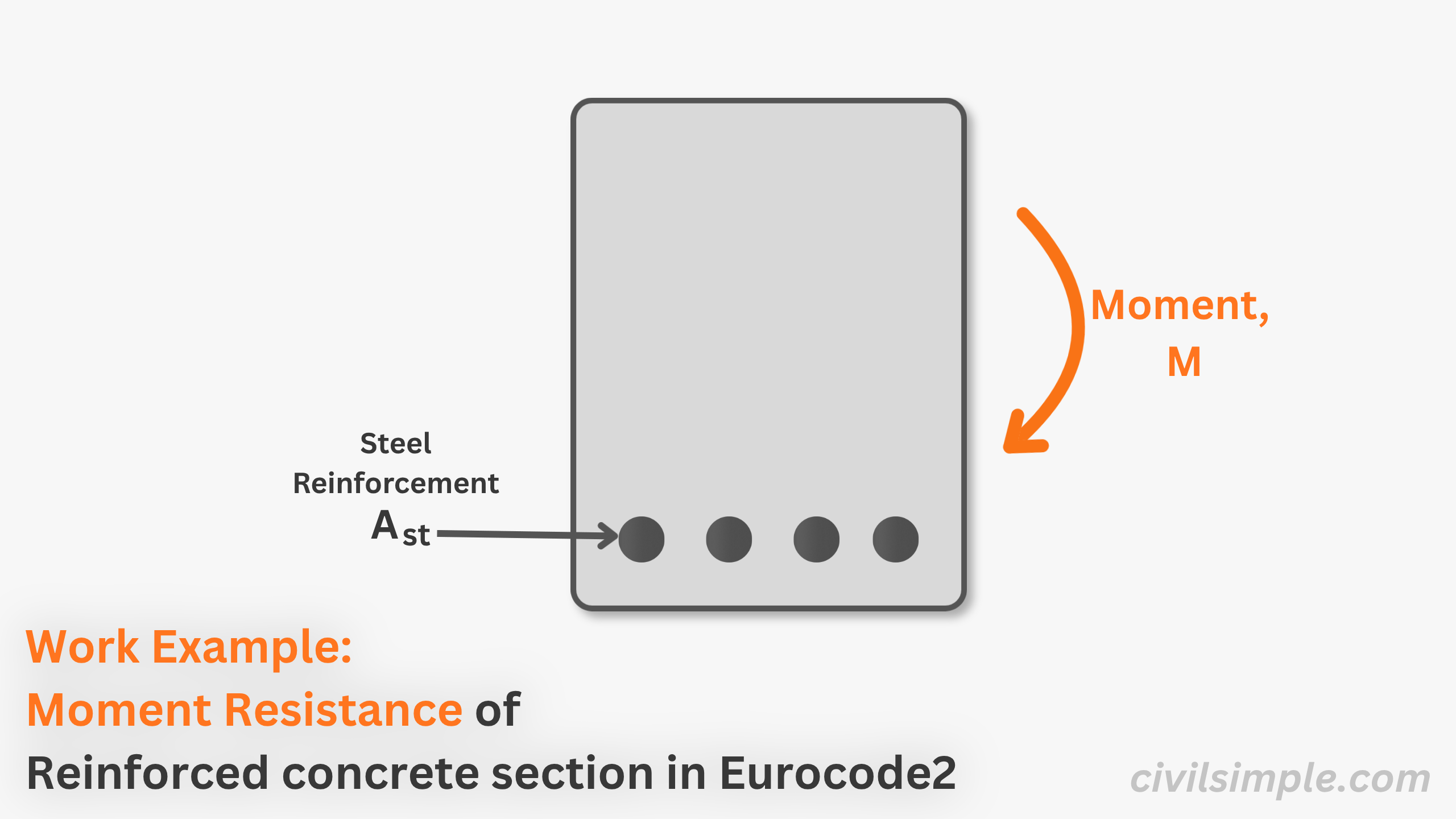
Work Example of Moment Resistance of Reinforced Concrete Section in Eurocode 2
A work example about moment resistance referencing to eurocode 2(BSEN1992-1-1:2004) for reinforced concrete section.
-
 work-example
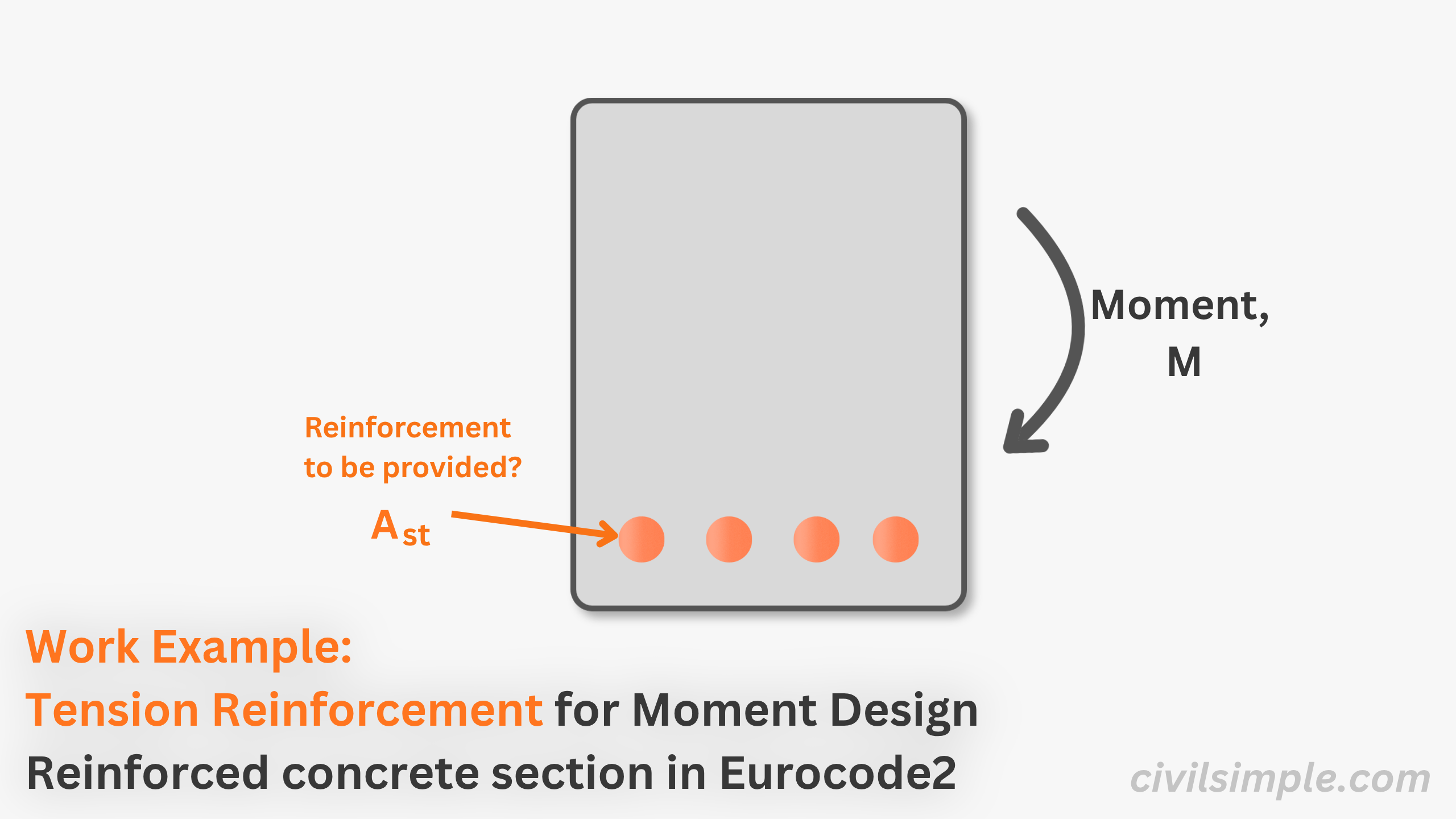
Work Example of Tension Reinforcement for Moment Design of Reinforced Concrete Section in Eurocode 2
A work example about tension reinforcement for moment design referencing to eurocode 2(BSEN1992-1-1:2004) for reinforced concrete section.
-
 formula
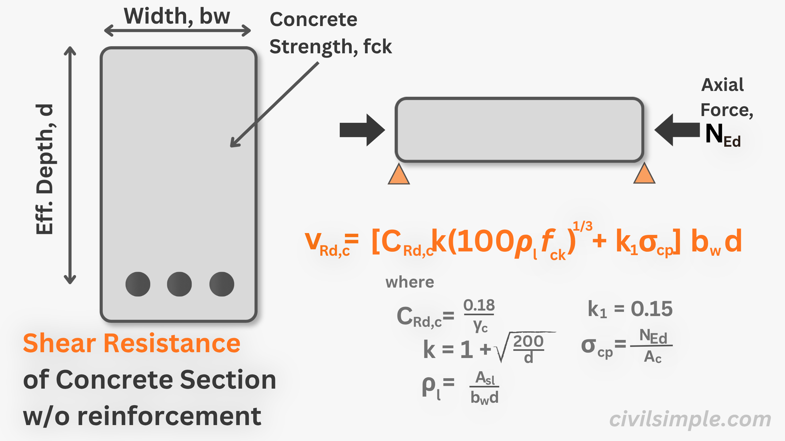
EC2 Shear Resistance of Concrete (V_Rd,c) Calculator & Explanation
Calculate the EC2 shear resistance of concrete (V_Rd,c) and learn how Eurocode 2 determines shear capacity without shear reinforcement.
-
 formula
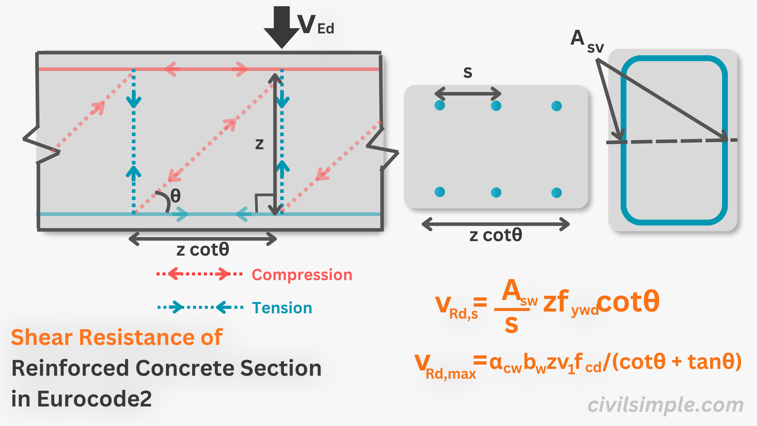
What is shear resistance of reinforced concrete section in Eurocode 2?
Learn the fundamentals of shear and shear resistance, including how to calculate the shear resistance of reinforced concrete sections in accordance with Eurocode 2. This article also covers the key influencing factors and the design steps for handling shear in different scenarios.
-
 proof
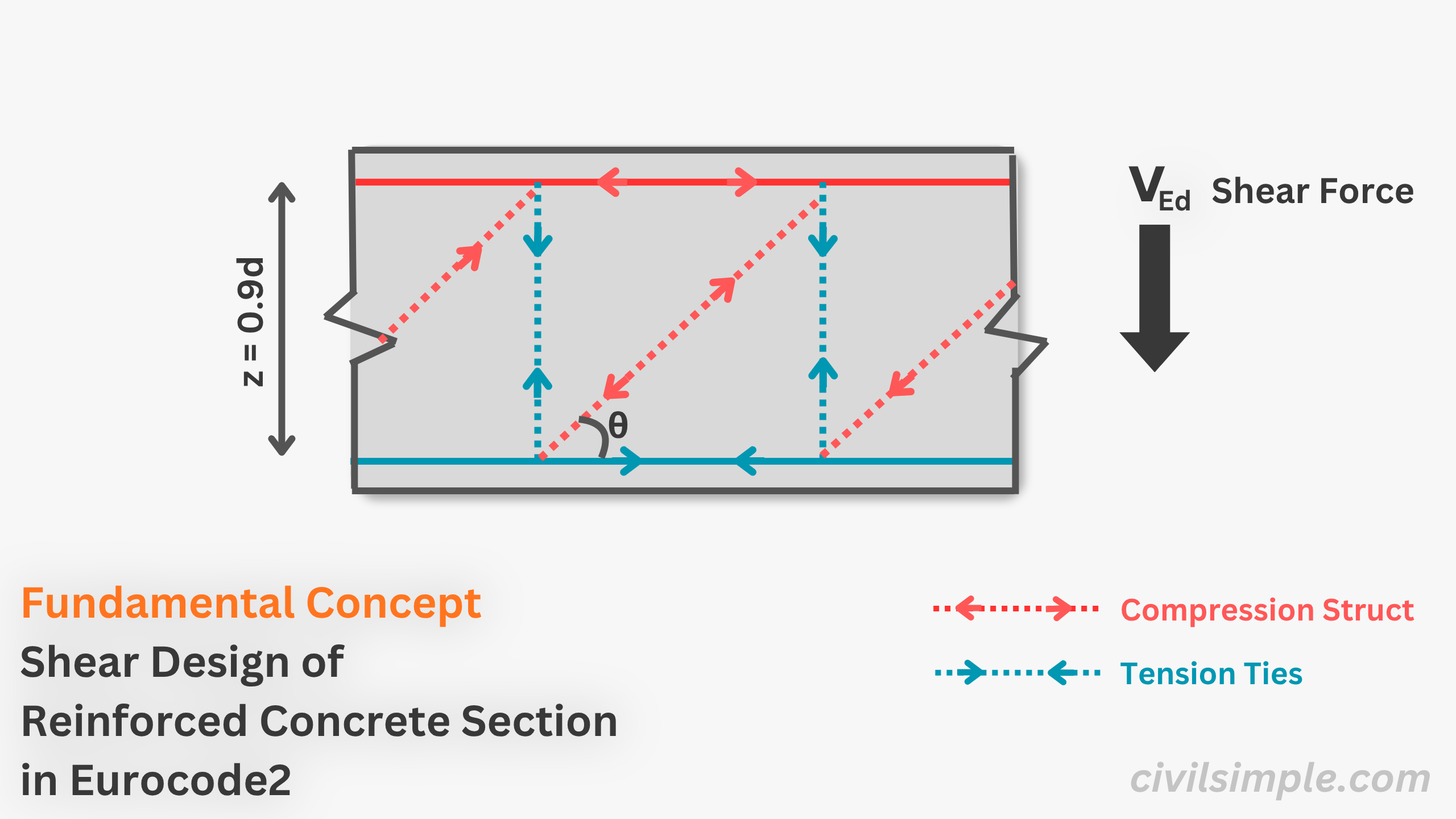
proofFundamental Concept of Shear Reinforcement Design of Reinforced Concrete Section in Eurocode 2
A overview about design method (Truss Model) used in eurocode 2 for shear design and corresponding derived of vertical shear reinforecement equations 6.8 and 6.9 of BSEN1992-1-1:2004.
-
 work-example
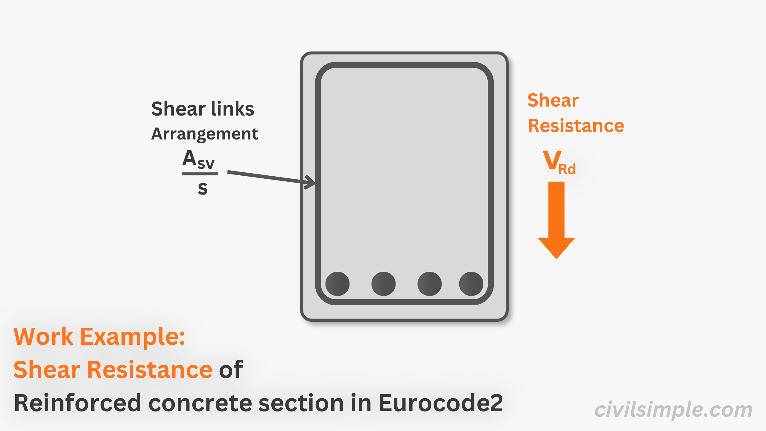
Work Example of Shear Resistance of Reinforced Concrete Section in Eurocode 2
A work example about shear resistance referencing to eurocode 2(BSEN1992-1-1:2004) for reinforced concrete section.
-
 work-example
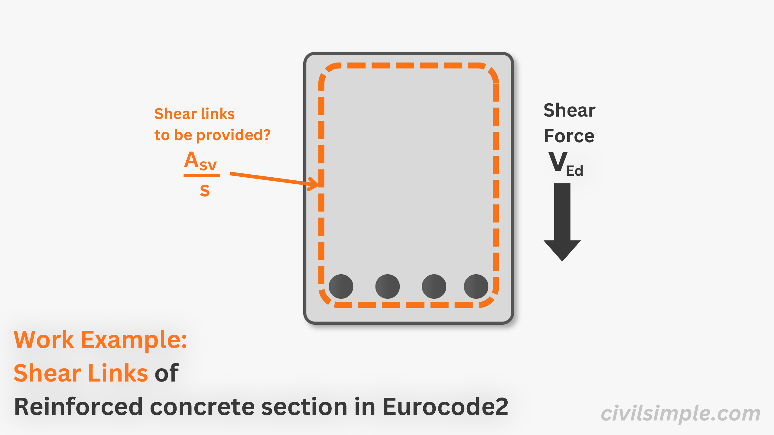
EC2 Shear Links Design - Worked Example
Worked example - shear links design for a 500×600 mm RC beam to Eurocode 2 (EC2). Step-by-step from V_Ed to Asw/s with suggested table of shear links arrangement.
-
 formula
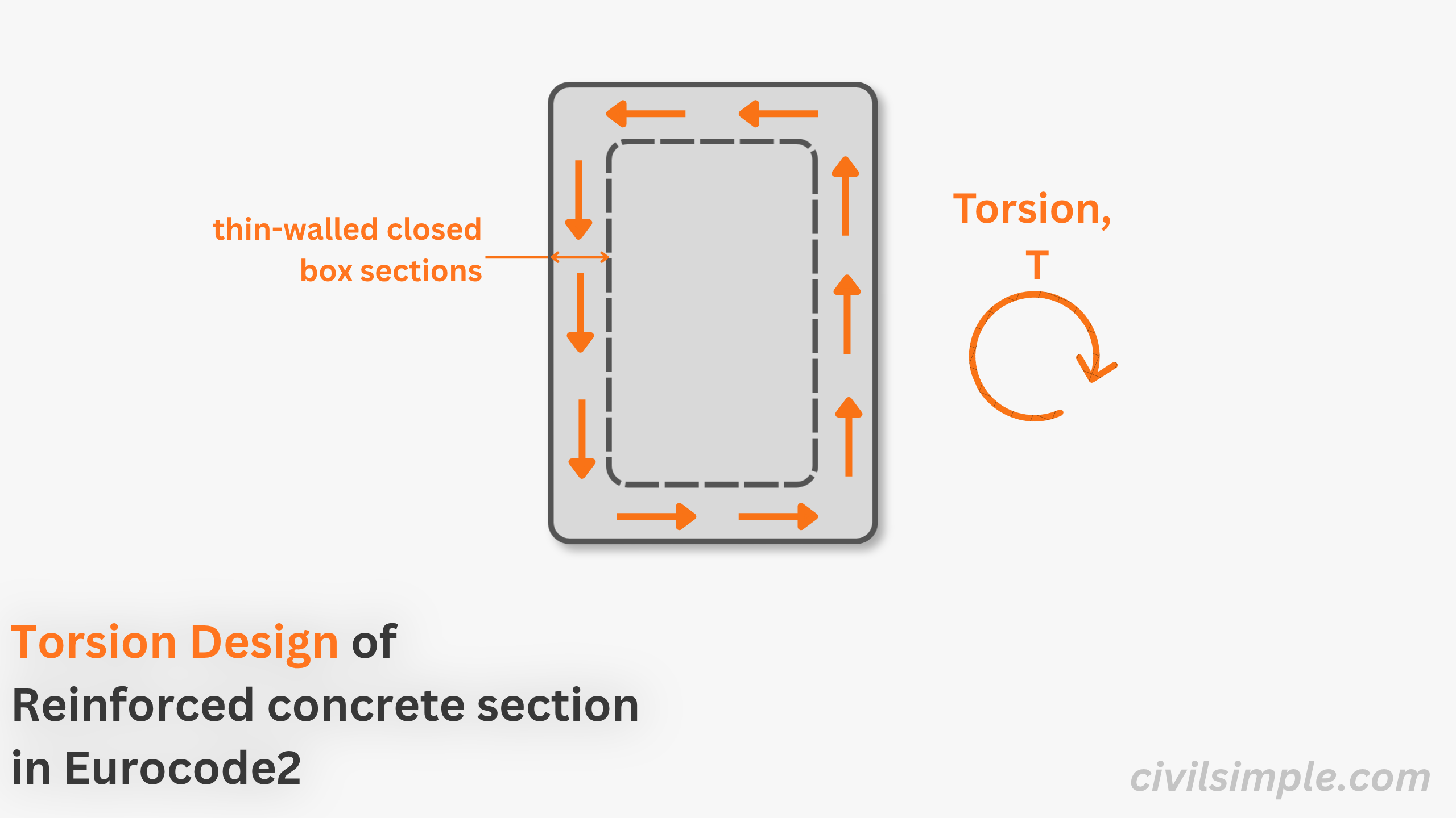
Torsion Design of Reinforced Concrete Section - Theory, Equations & Calculation Guide (EC2)
Learn EC2 torsion design for reinforced concrete beams with interactive SVG diagrams, design equations, and a step-by-step calculation guide.
-
 proof
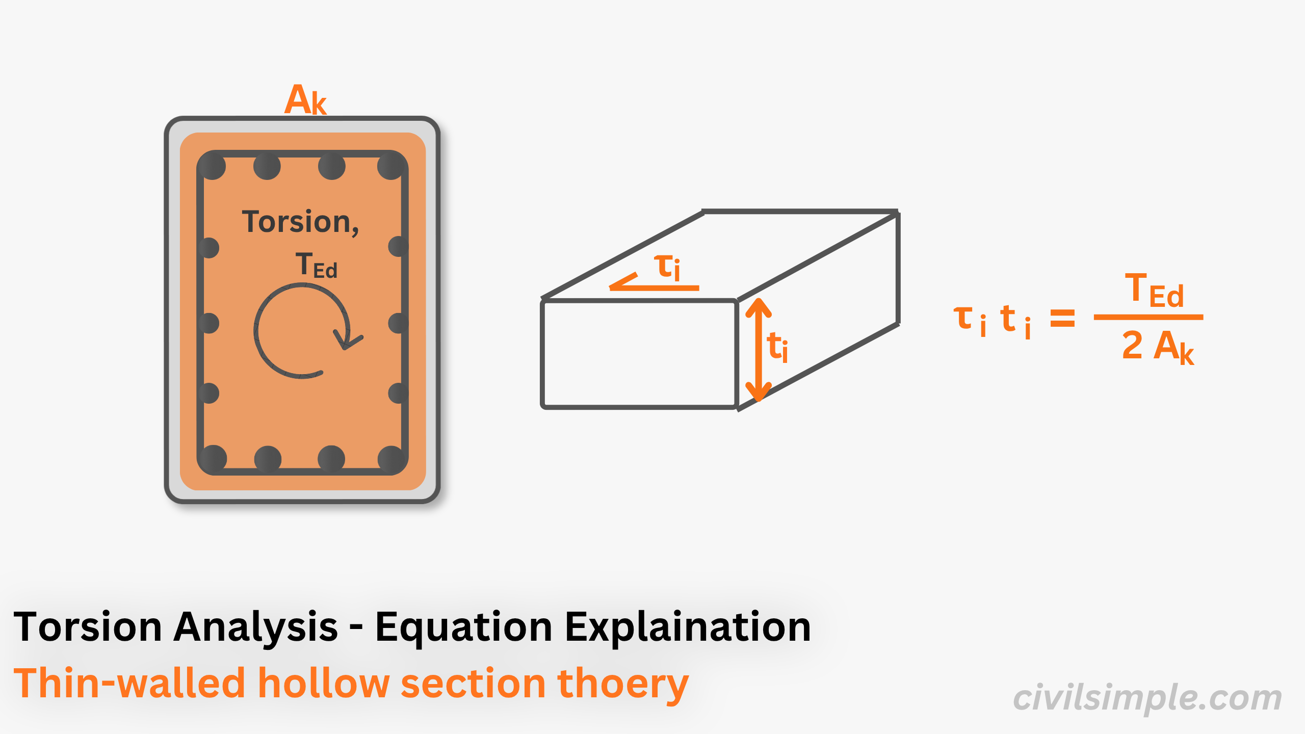
proofThin-Walled Torsion Equation (EC2) - Derivation & Interactive Guide
Learn the derivation of the EC2 thin-walled torsion equation through interactive SVG diagrams, shear flow, and force equilibrium explained step by step.
-
 work-example
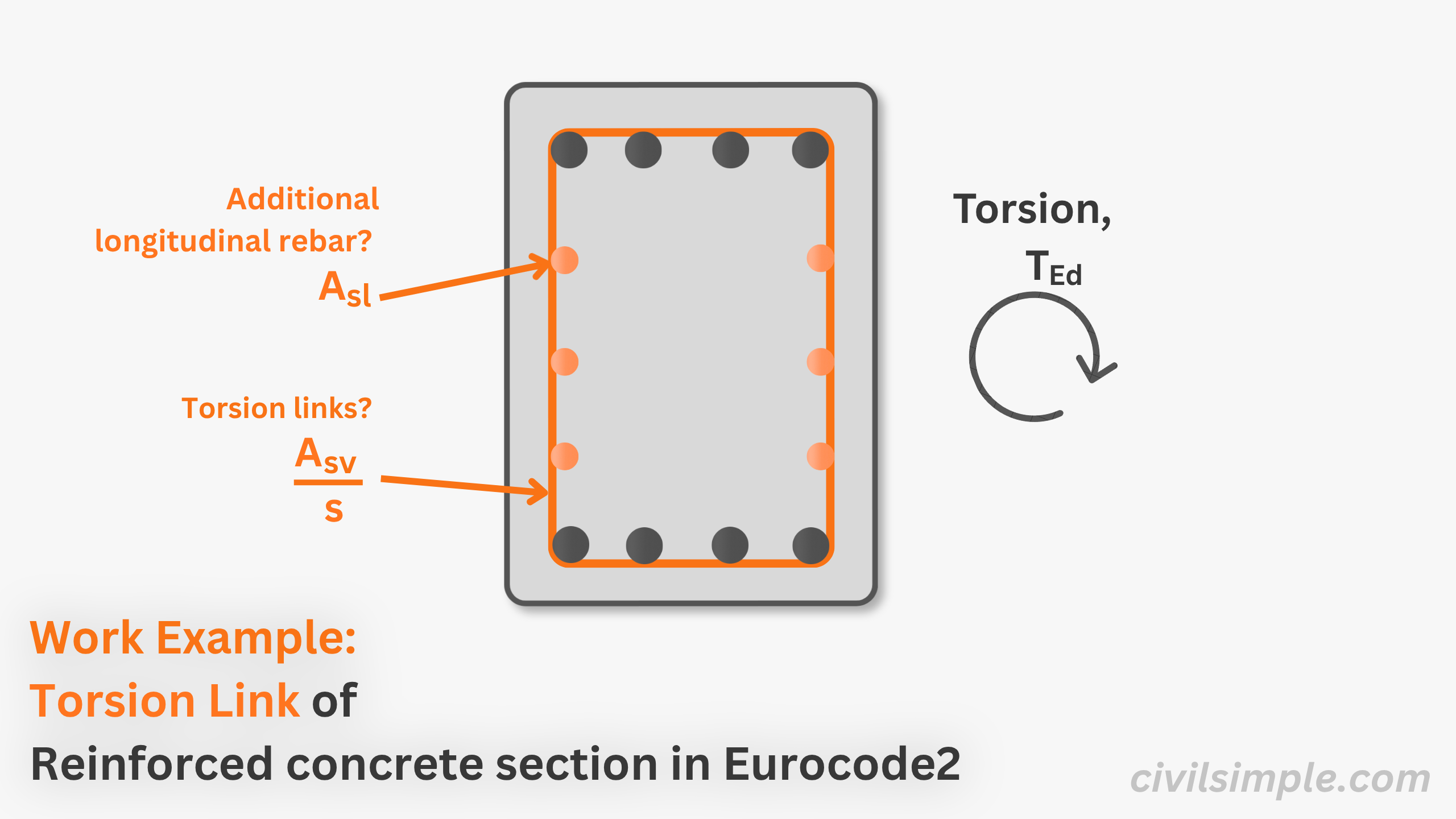
EC2 Torsional Link Design - Worked Example
Worked example - torsional link design for a 500×600 mm RC beam to Eurocode 2 (EC2). Step-by-step from T_Ed to Asw/s using the closed-section truss model.
-
 glossary
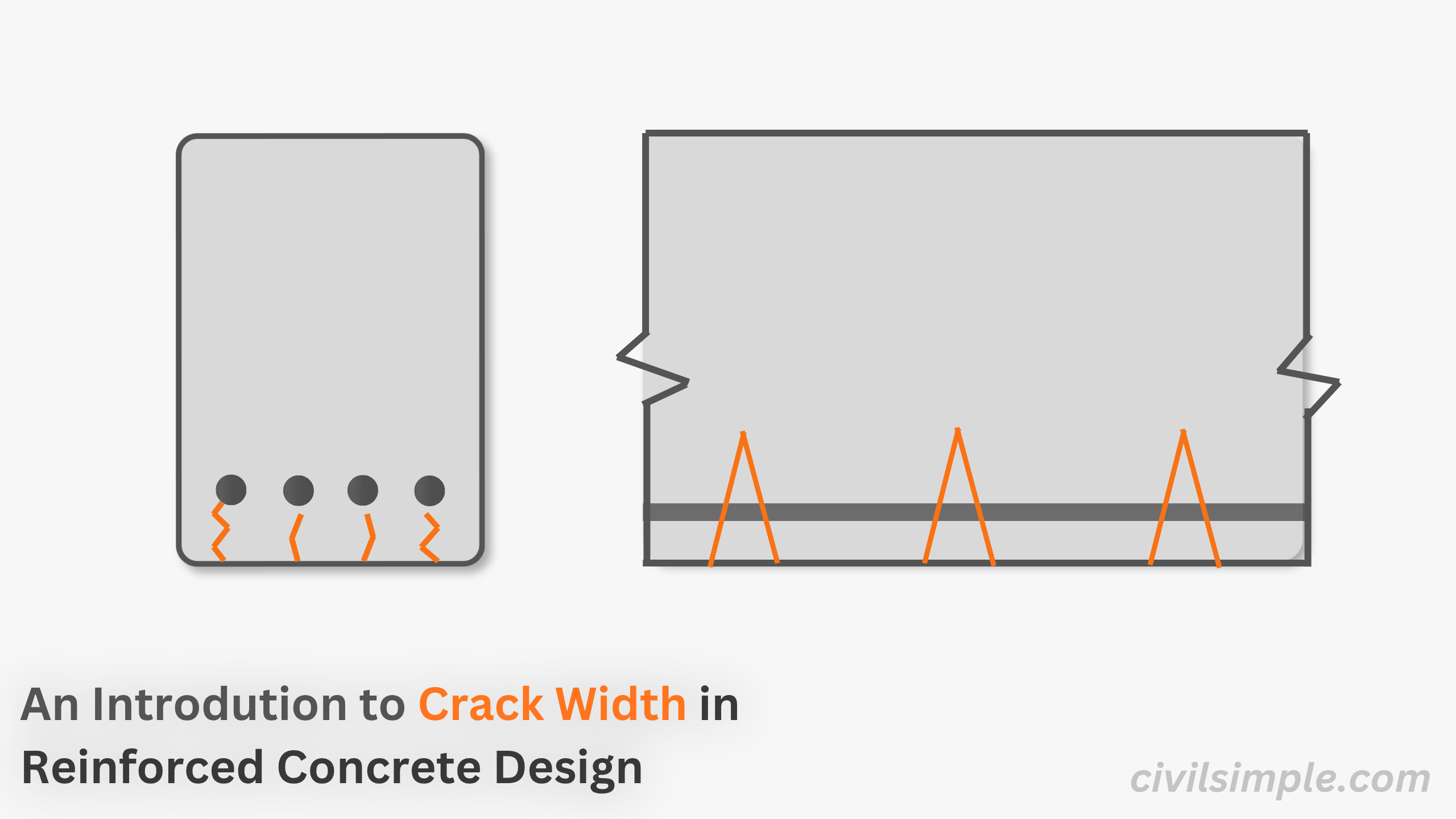
An Introduction to Crack Width in Reinforced Concrete Design
Discover the core concepts of crack width in reinforced concrete design. Learn why concrete cracks, SLS serviceability checks, and how it impacts durability.
-
 formula
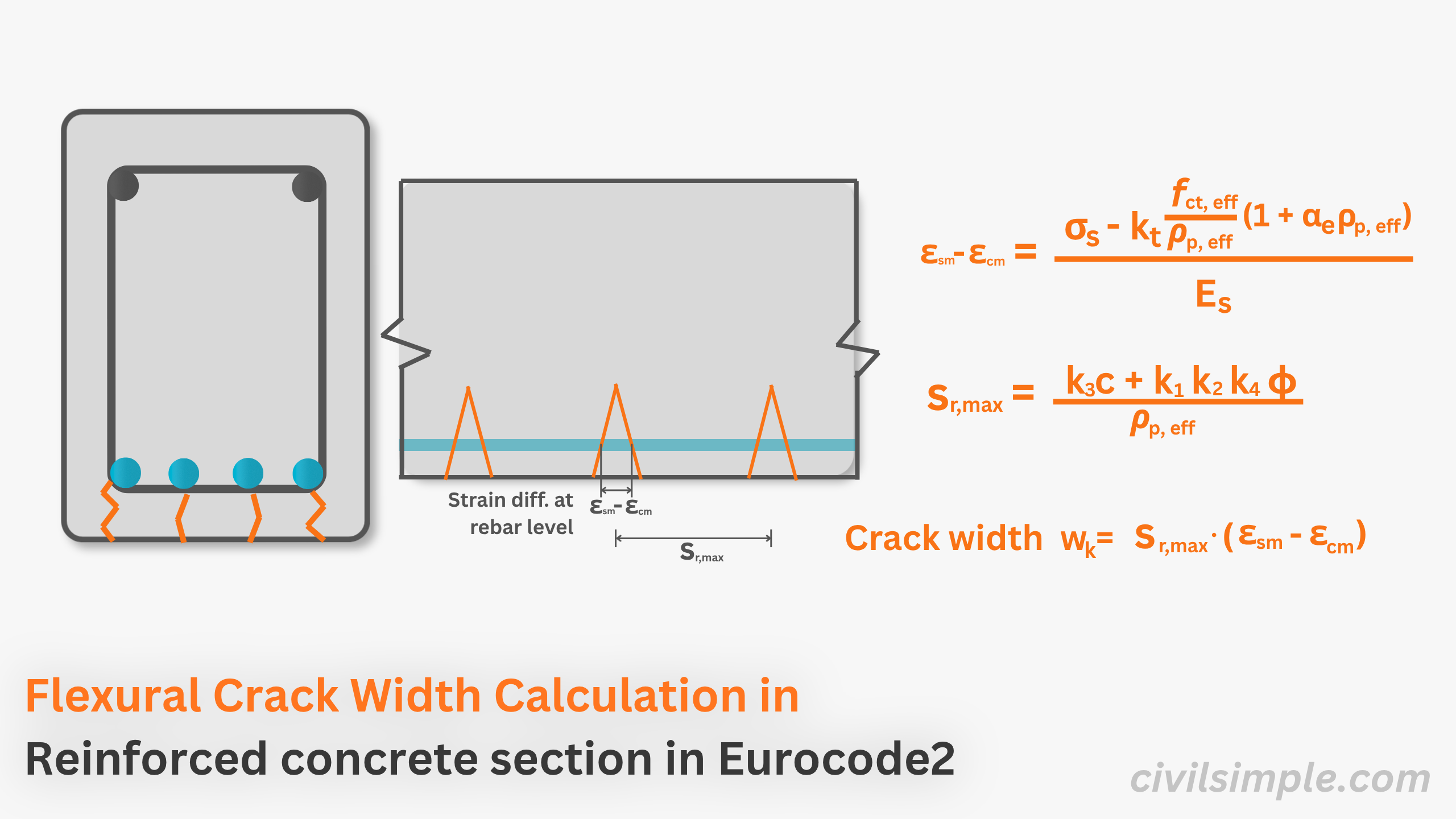
Flexural Crack Width Calculation in Concrete in Eurocode 2
Learn how to calculate flexural crack width in reinforced concrete. This guide covers key factors, detailed formulas, and a step-by-step design workflow.
-
 work-example
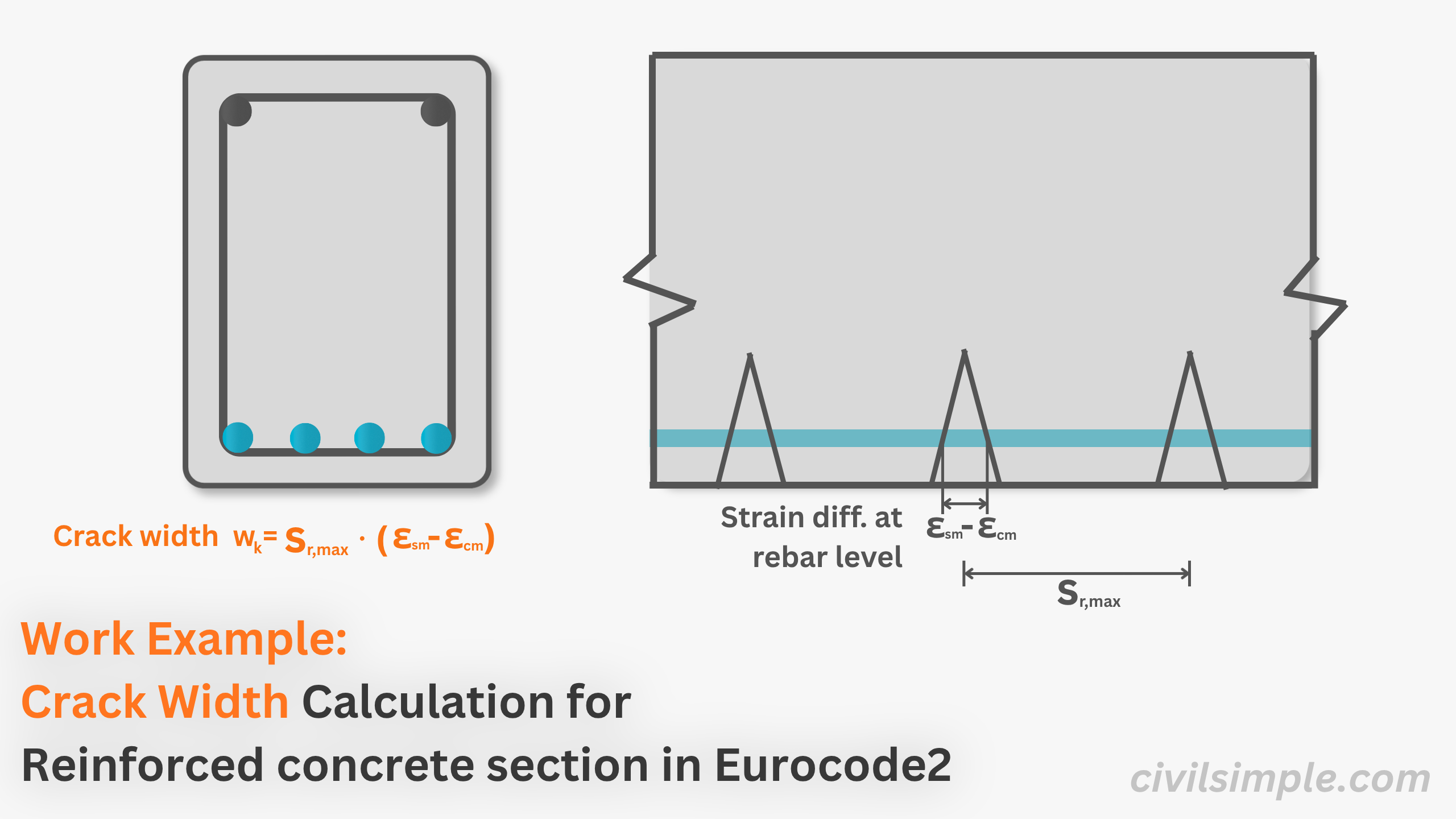
Crack Width - EC2 Worked Example
Worked example - crack width calculation for a 500×700 mm RC beam to Eurocode 2 (EC2). Step-by-step from bending moment M_Ed to crack width w_k.
-
 glossary
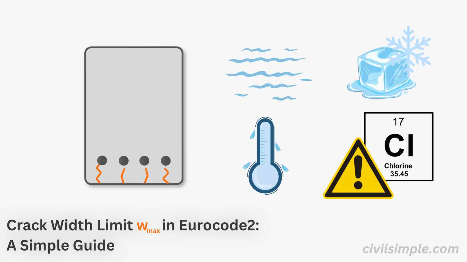
Crack Width Limits in Eurocode 2 - A Simple Guide
Understand crack control in Eurocode 2 (EC2), including crack width limits, exposure classes, and the requirements for durable reinforced concrete.
-
 work-example
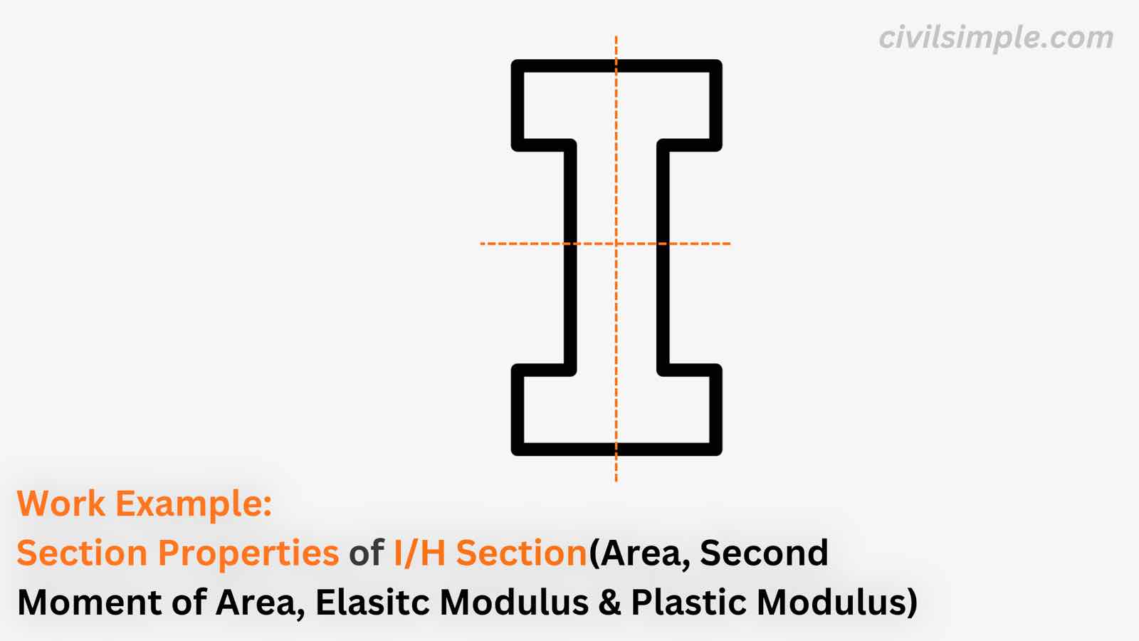
Work Example of Calculation of Section Properties of I Section
A work example about calculation of section properties of Rectangular Hollow Section (RHS) including area, second moment of area, elastic modulus and plastic modulus.
-
 work-example
Work Example of Calculation of Section Properties of CHS
A work example about calculation of section properties of Circular Hollow Section (CHS) including area, second moment of area, elastic modulus and plastic modulus.
-
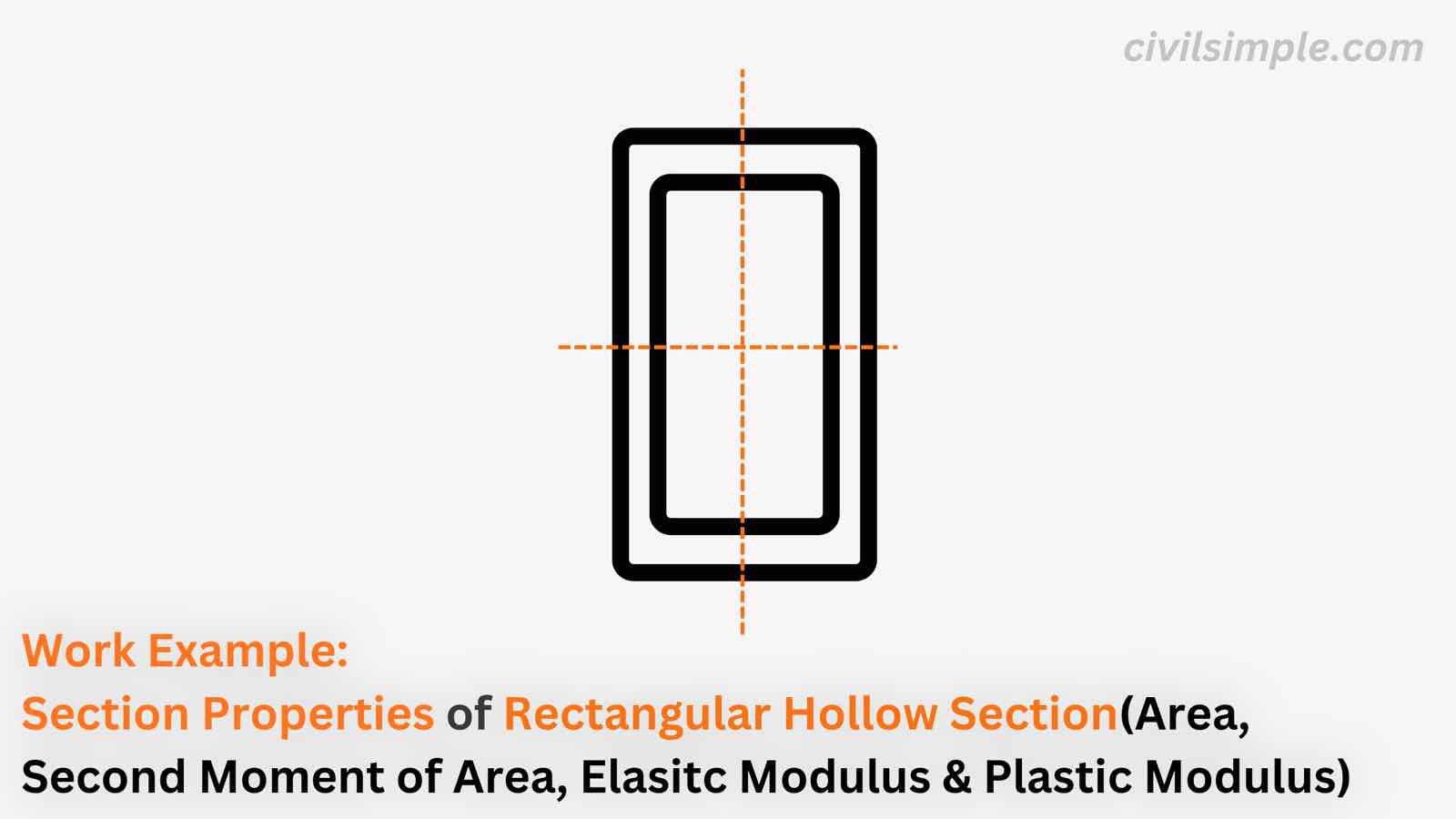 work-example
Work Example of Calculation of Section Properties of RHS
A work example about calculation of section properties of Rectangular Hollow Section (RHS) including area, second moment of area, elastic modulus and plastic modulus.
-
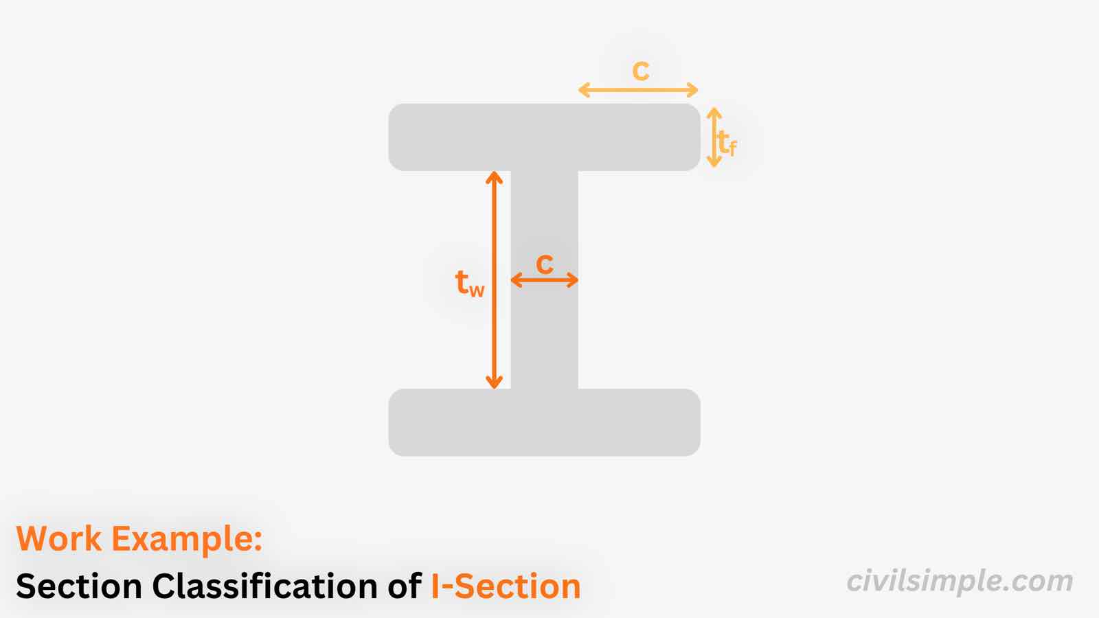 work-example
Work Example of Section Classification of I-Section in Bending and Compression
A worked example classifying a hot-rolled I-section (UB) under both pure bending and pure compression — showing how the same section goes from Class 1 (plastic) to Class 4 (slender) as the web limits tighten under uniform compression.
-
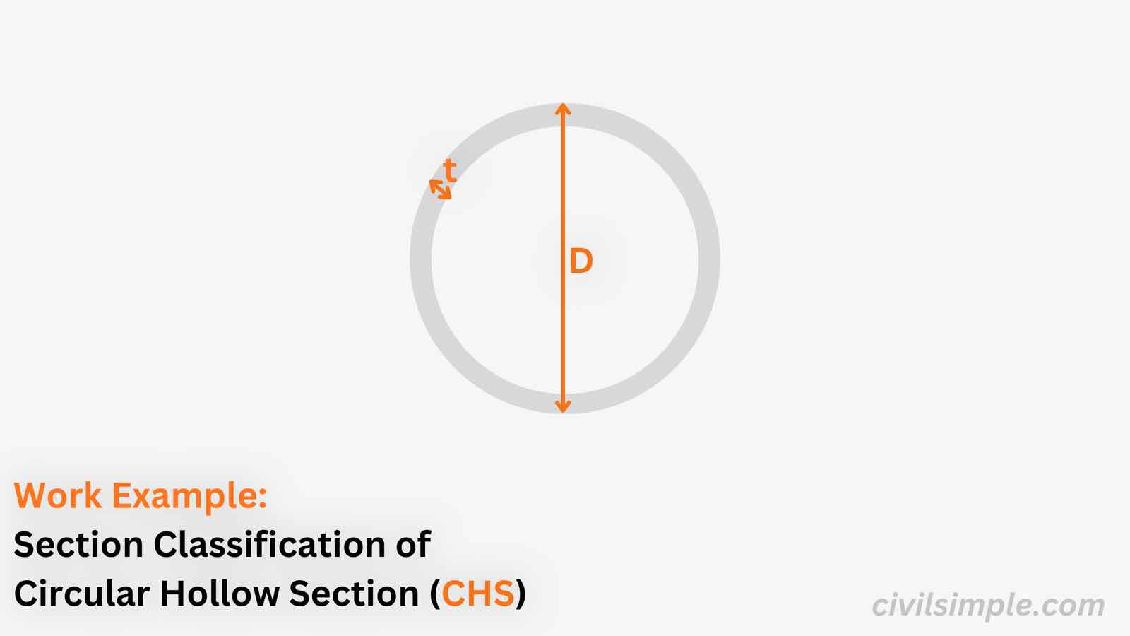 work-example
Work Example of Section Classification of CHS in Bending and Compression
A worked example classifying a Circular Hollow Section (CHS) under both pure bending and pure compression — a single D/t check that gives the same class (Class 2) under both stress states.
-
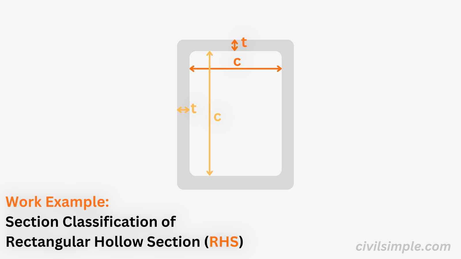 work-example
Work Example of Section Classification of RHS in Bending and Compression
A worked example classifying a Rectangular Hollow Section (RHS) under both pure bending and pure compression — showing how the web's limits tighten under uniform compression, and why this stocky section stays Class 1 in both.
-
 work-example
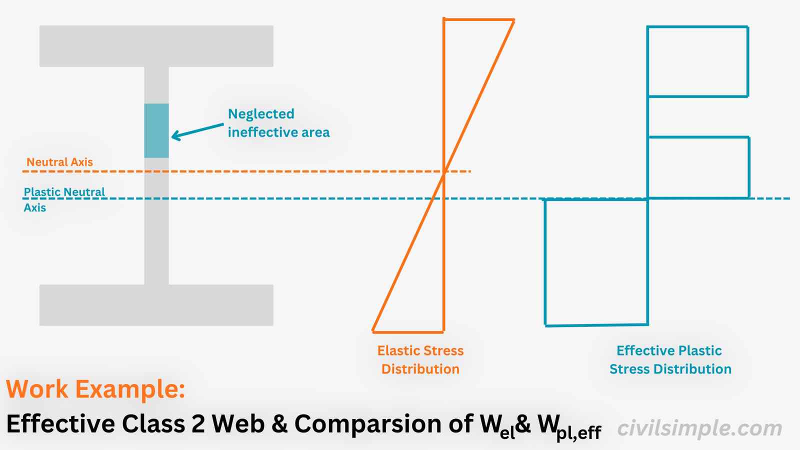
Work Example of Bending Resistance of Effective Class 2 Web for a Steel I-Section (Eurocode 3)
A worked example of the effective Class 2 method (EN 1993-1-1 6.2.2.4) for a welded steel I-section in S355 with a Class 1 flange and a Class 3 web - calculating the effective plastic modulus W_pl,eff and the enhanced bending resistance M_pl,eff,Rd, compared with the elastic Class 3 value.
-
 work-example
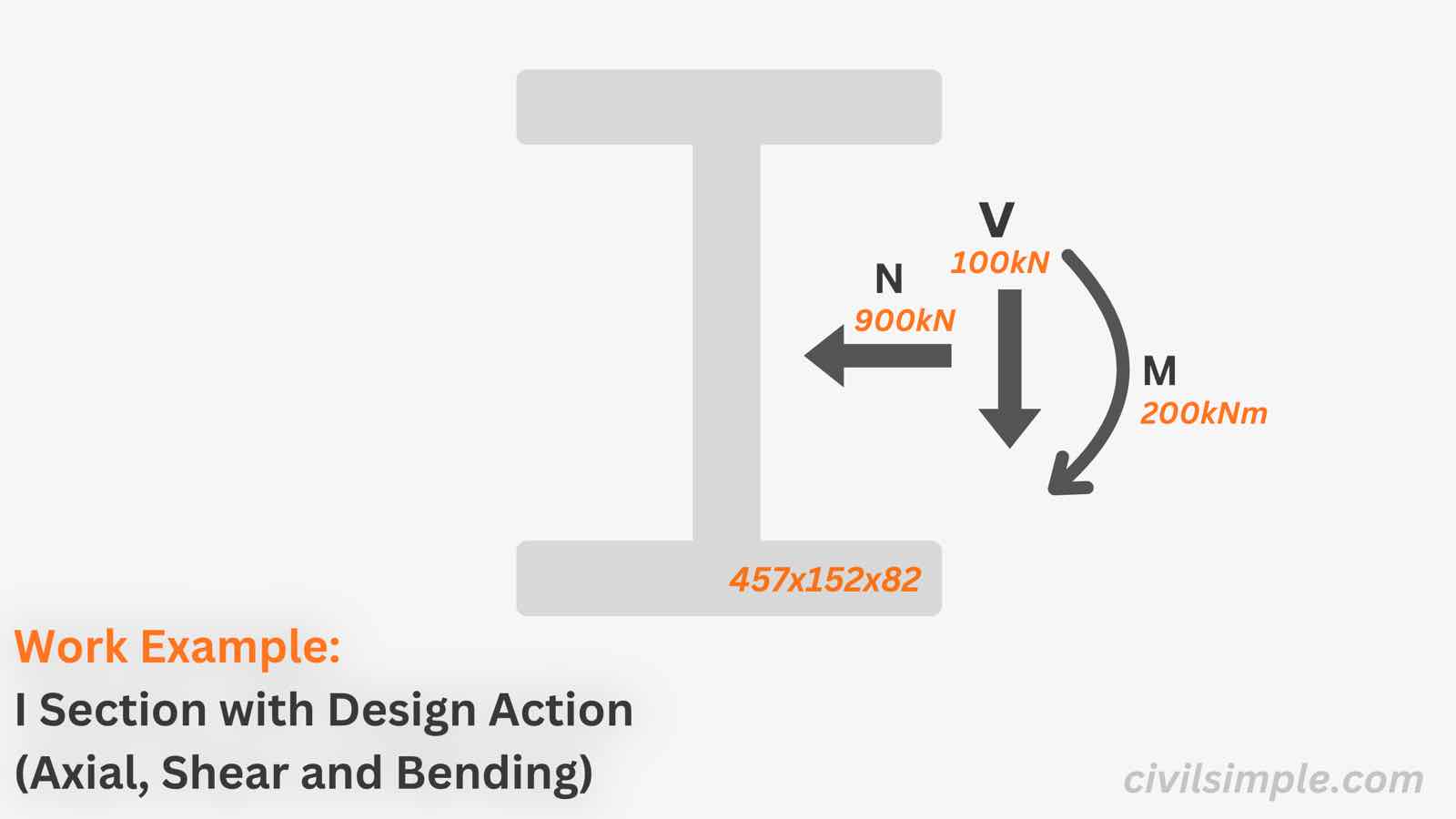
Work Example of Steel Section Check with Design Actions - I-Section (Eurocode 3)
A worked example of the full cross-section resistance check of a UB 457x152x82 in S355 under 900 kN compression, 100kN Shear and 200 kNm major-axis bending — classification, the Class 4 effective-area compression check, the Class 1 bending check and the reduced moment resistance for combined bending, shear and axial force.
-
 work-example
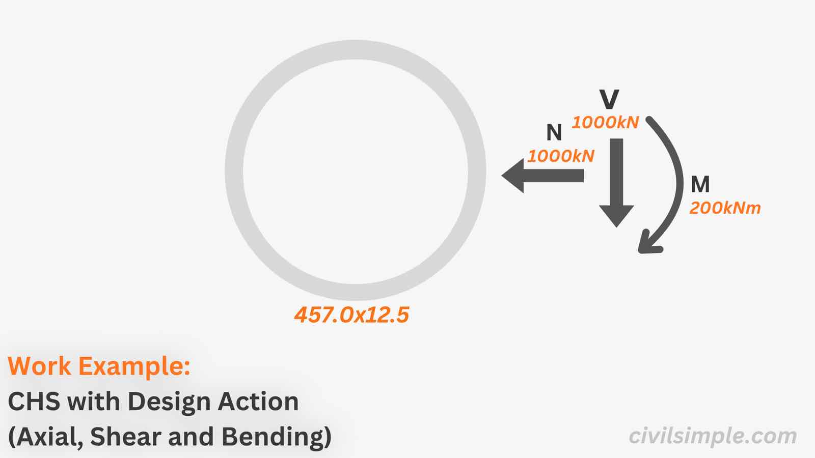
Work Example of Steel Section Check with Design Actions - CHS (Eurocode 3)
A worked example of the full cross-section resistance check of a CHS 457.0x12.5 in S355 under 1000 kN compression, 1000kN Shear and 200 kNm major-axis bending — classification, compression check, shear check, bending check and combined bending, shear and axial force check.
-
 work-example
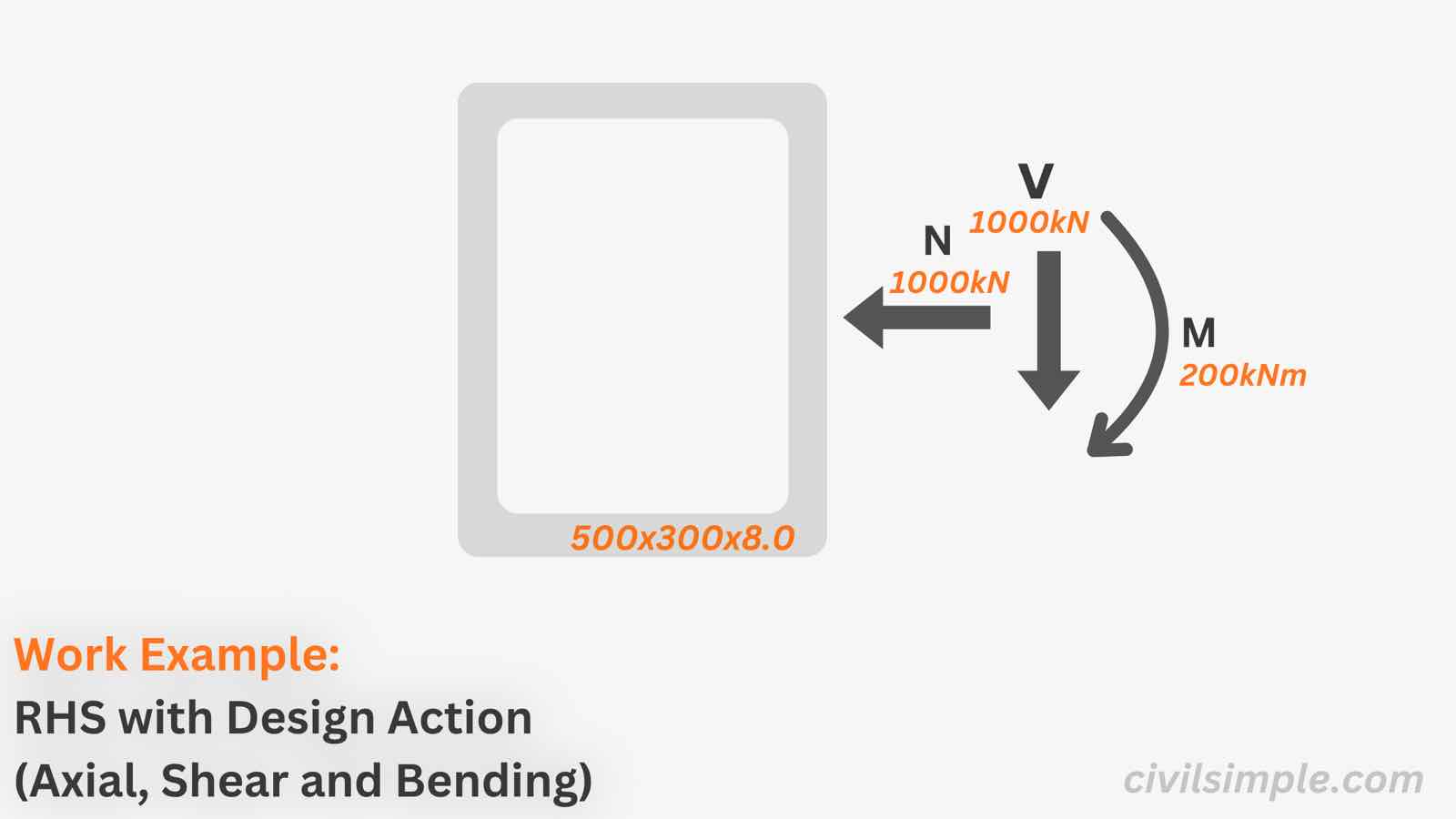
Work Example of Steel Section Check with Design Actions - RHS (Eurocode 3)
A worked example of the full cross-section resistance check of a RHS 500x300x8.0 in S355 under 1000 kN compression, 1000kN Shear and 200 kNm major-axis bending — classification, compression check, shear check, bending check and combined bending, shear and axial force check.
-
 work-example
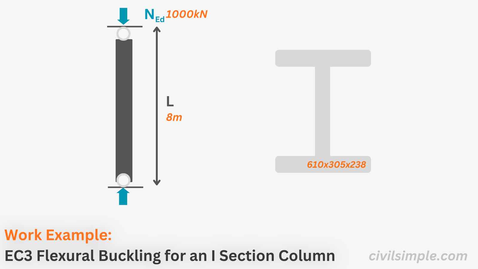
Work Example: Compression and Buckling Check of an I-Section Column to Eurocode 3
A complete worked example of the compression and flexural buckling check of a 610x305x238 UB column in S355 under 1,000 kN design compression over an 8.0 m buckling length to Eurocode 3 (EN 1993-1-1) — section properties, classification, slenderness, buckling curves, the reduction factor χ, the buckling resistance and the final utilisation ratio.
-
 work-example
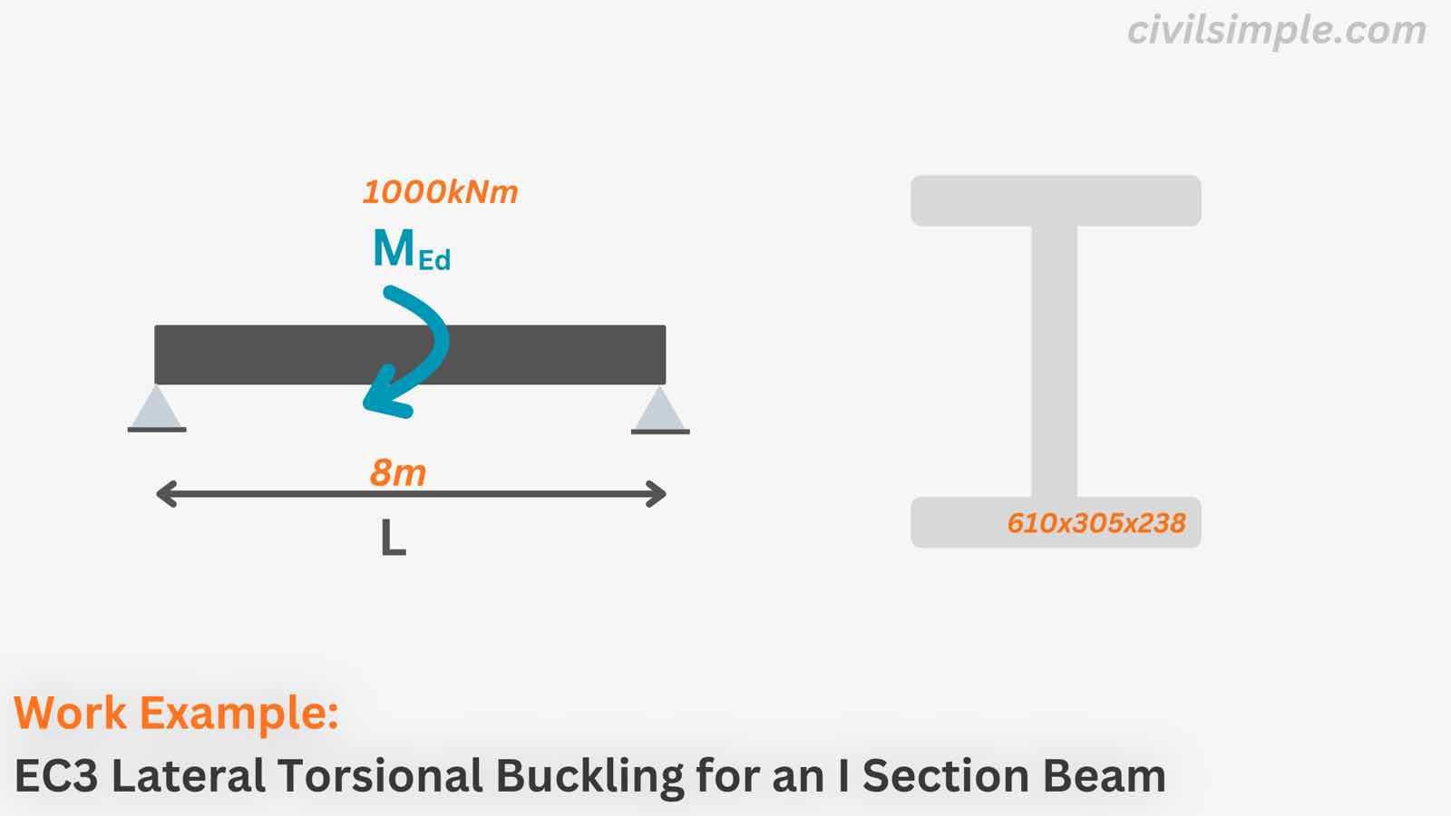
Work Example: Lateral Torsional Buckling Check of an I-Section Beam to Eurocode 3
A complete worked example of the lateral-torsional buckling check of a 610x305x238 UB beam in S355 under a 1,000 kNm design major-axis moment over an 8.0 m laterally unrestrained span to Eurocode 3 (EN 1993-1-1) — section properties, classification, the elastic critical moment Mcr, slenderness, buckling curve c, the reduction factor χLT and the final utilisation ratio.
-
 work-example
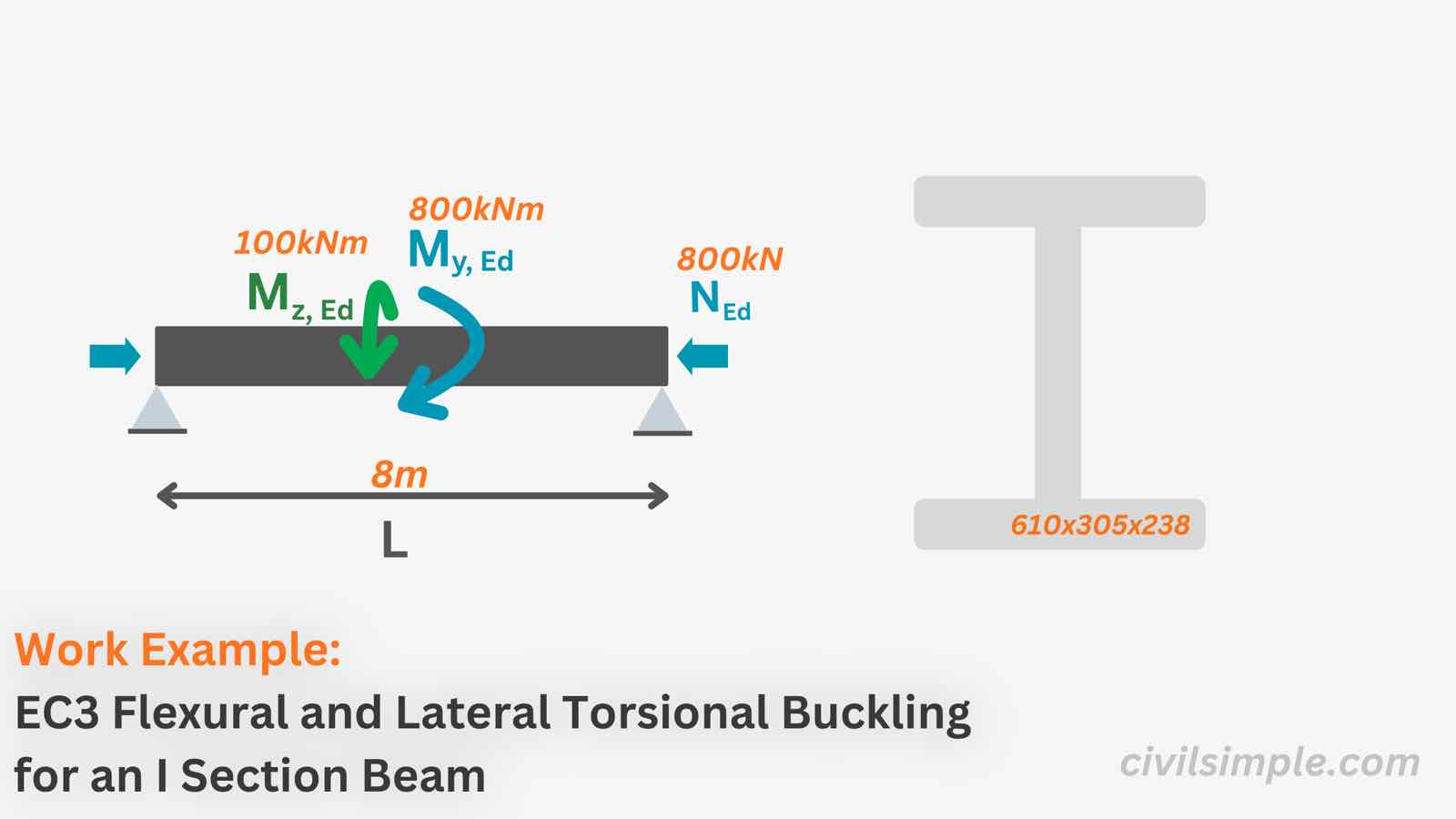
Work Example: Combined Compression and Bending Buckling Check of an I-Section Beam-Column to Eurocode 3
A complete worked example of the combined compression and bending buckling check of a 610x305x238 UB beam-column in S355 under 800 kN compression and 800 kNm major-axis plus 100 kNm minor-axis bending to Eurocode 3 (EN 1993-1-1) — section classification, cross-section checks, flexural and lateral-torsional buckling, and the interaction equations 6.61 and 6.62 with the Annex B interaction factors.