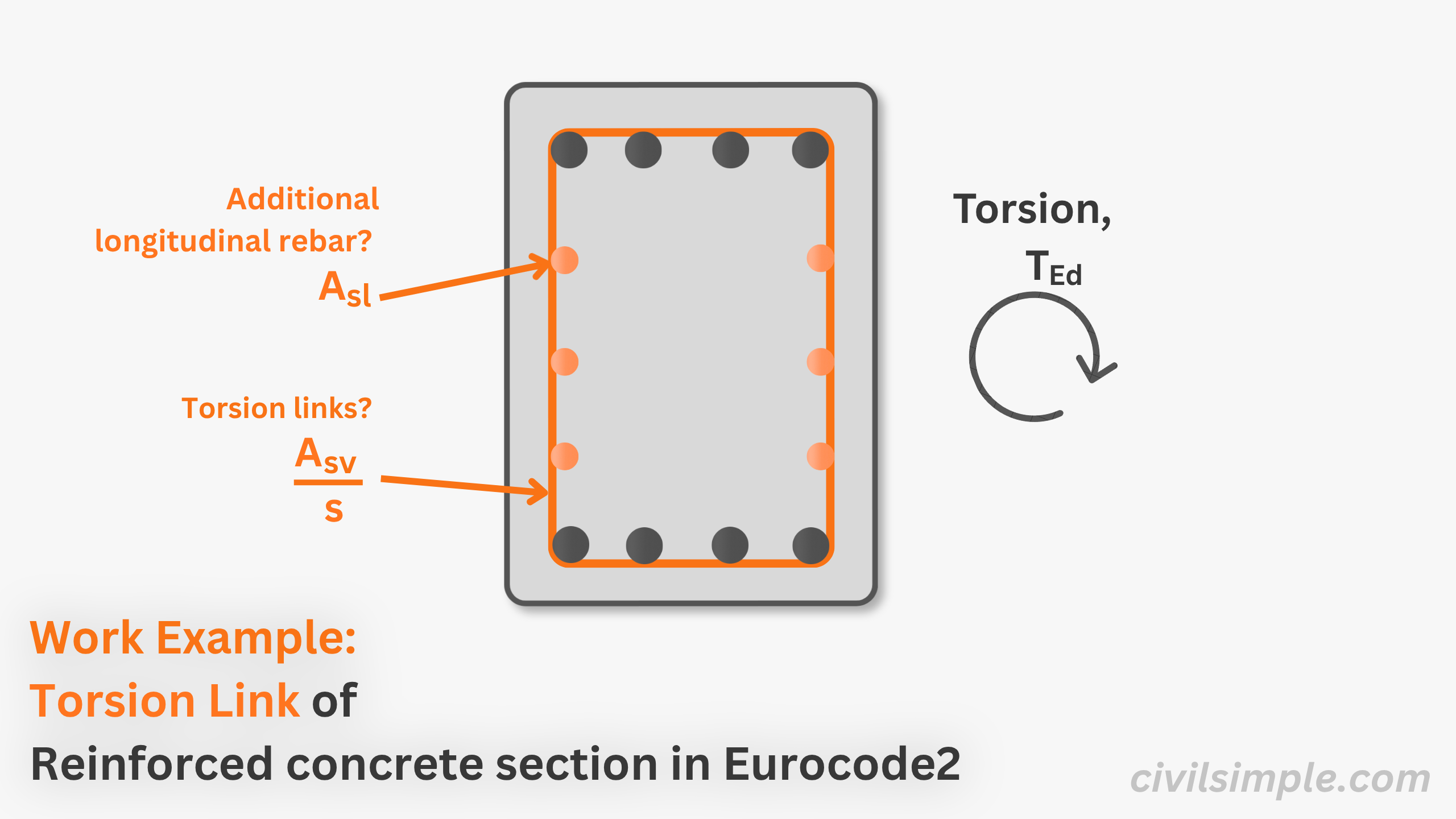
Worked example - torsional link design for a 500×600 mm RC beam to Eurocode 2 (EC2). Step-by-step from T_Ed to Asw/s using the closed-section truss model.
CivilSimple Team
Published Jun 24, 2026
5 min read
Figure 1 — Work Example of Torsion Link of Reinforced Concrete Section
👋 Introduction
The calculation of torsion links with a given section and torsion moment is not straight-forward. For some basic idea, you can refer to this article. For quick steps guide, below is an example, hope you find it helpful.
📐 Design Data
Below are the design information of the torsion design of the section.
Geometry
Section
Width
500mm
Height
600mm
Reinforcement
Tension Area
1470 mm²
Design Action
Torsion Tx
100kNm
Shear Fy
50kN
Material
Concrete
Strength
30 MPa
Rebar
Strength
500 MPa
Assumption
=
=
=
🔢 Calculation Steps
*Unless otherwise specified, all clauses and equations quoted herein are based on BS EN 1992-1-1:2004.
1. Determine the equivalent hollow thin-wall section for torsional analysis
Effective thickness of walls(Fig. 6.11)
=
=
=
Area enclosed by line of wall(Fig. 6.11)
=
=
=
Perimeter for line of wall(Fig. 6.11)
=
=
=
2. Determine if concrete is sufficient for compression
2.1Determine compression strut angle
Strength Reduction Factor of Concrete(Eq. 6.6N)
=
=
=
Effective Depth
=
=
=
Design Shear Stress
=
=
=
Torsion Shear Stress
=
=
=
Inclined angle of compression strut
=
=
=
2.2Determine the max. tosional resistance and max. shear resistance
Maximum Torsional Resistance(Eq. 6.30)
=
=
=
Maximum Shear Resistance(Eq. 6.9)
=
=
=
2.3Check if concrete section in compression is adequate
Combine Shear and Torsion Check(Eq. 6.29)
=
=
=
∴ Current concrete section is sufficient for compression.
3. Determine if concrete alone w/o links/reinforcement is sufficient for tension
3.1Determine torsional resistance w/o links
Torsional Resistance w/o links(Eq. 6.26)
=
=
=
3.2Determine shear resistance w/o links
Concrete Factor(N.A. Cl.6.2.2(1))
=
=
=
Reinforcement Ratio(Eq. 6.6N)
=
=
=
Depth factor(Cl.6.2.2(1))
=
=
=
Minimum Shear Resistance
=
=
=
Design Shear Resistance(Eq. 6.2a)
=
=
=
3.3Check if concrete section in tension is adequate
Combine Shear and Torsion Check(Eq. 6.31)
=
=
=
∴ Solely concrete resistance is not sufficient for tension, torsional links required.
4. Determine the required torsional reinforcement
Required Area for Torsional Reinforcement
=
=
=
Maximum Vertical Rebar Spacing(Eq. 9.2.3(3))
=
=
=
Suggested Torsion Link Arrangement
Bar Dia.
spacing
As/s(mm2/m)
notation
8
125
0.4021
R8@125
12
125
0.9048
R12@125
16
125
1.6085
R16@125
5. Determine the required longitudinal reinforcement
Additional Long. Reinforcement for Torsion(Eq. 6.8)
=
=
=
Suggested Longitudinal Arrangement
Potential Arrangement
area (mm²)
utilization (%)
8T20
2513.27
80.8
12T16
2412.74
84.2
6T25
2945.24
69
∴ The Minimum Shear Rebar Area is 0.84 mm2/m and suggested shaer rebar arrangement is R8@100 2legs.
📄 Need a Full Design Check Report?
If you want similiar calculation analysis with your own design data, feel free to try our application, what you need is just the design data value, and a ready-to-submit design PDF report will be generated in a minute.
The ready-to-submit PDF Report is not generated by AI but programmed by chartered engineer, which is accurate, no hallucination and same input same output.
The CivilSimple Team writes practical engineering guides for the profession and the curious. All articles are reviewed for technical accuracy before publication.