Worked Example - Bending Resistance of Effective Class 2 Web (Eurocode 3)
A worked example of the effective Class 2 method (EN 1993-1-1 6.2.2.4) for a welded steel I-section in S355 with a Class 1 flange and a Class 3 web - calculating the effective plastic modulus Wpl,eff and the enhanced bending resistance Mpl,eff,Rd, compared with the elastic Class 3 bending resistance Mel,Rd of same section.
CivilSimple Team
Published Aug 28, 2026
9 min read
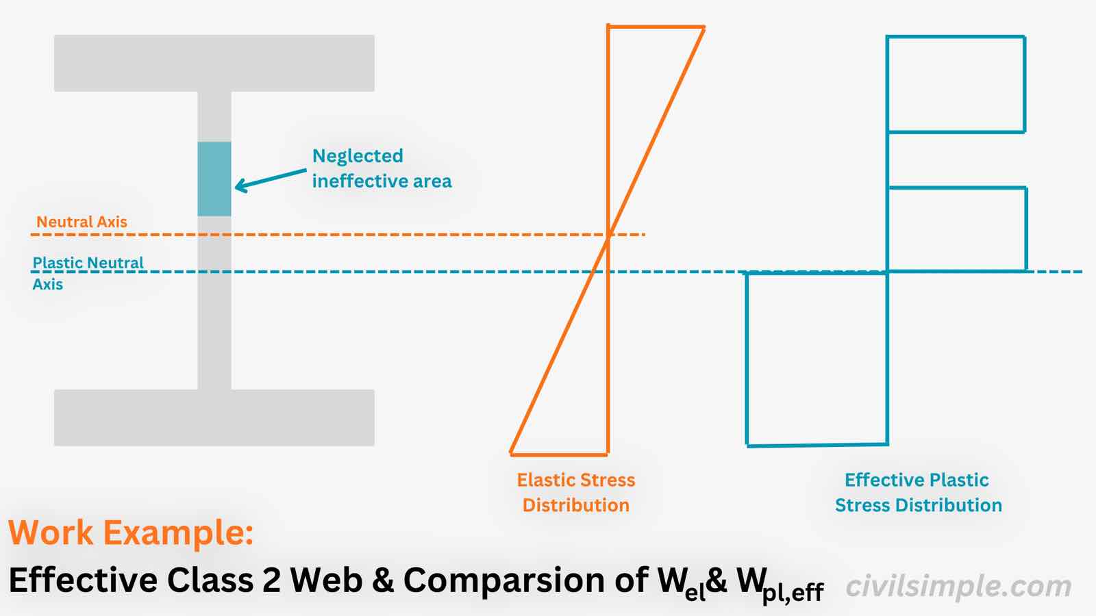
Figure 1 — A welded I-section with a Class 1 flange and a Class 3 web - can be considered using effective plastic modulus over elastic modulus for bending resistance.
👋 Introduction
Effective Class 2 is a bending resistance enhancement in Eurocode 3 for steel I-sections where the flange is Class 1 or 2 but the web is only Class 3. Instead of dropping all the way to the elastic modulus Wel (the Class 3 default), the eurocode3 lets us recover most of the plastic capacity by replacing the web's compression zone with two 20ε·tw effective strips and using an effective plastic modulus Wpl,eff. EN 1993-1-1 Cl.6.2.2.4(1)
In this worked example we take a welded plate girder (600×200×15×8) in S355 under pure bending. Its flange is comfortably Class 1 but its web just misses Class 2, so the section is normally Class 3 — but allow to apply the effective Class 2 method.
📐 Design Data
Below are the design data of the welded I-section, which we will classify and then check in bending using the effective Class 2 method.
Steel Section
Type
Welded I-section (plate girder)
Breadth, b
200mm
Height, h
600mm
Flange Thickness, tf
15mm
Web Thickness, tw
8mm
Weld / haunch zone, s
4mm
Material
Steel Grade
S355
Yield Strength, fy
355 N/mm²
Partial Factor, γM0
1.0
🔢 Calculation Steps
*Below uses Eurocode3 symbols and limits.
Step 1 — Classify flange and web
The flange is an outstand in compression (checked against 9ε / 10ε / 14ε); the web is an internal element in bending (checked against 72ε / 83ε / 124ε). The worst class governs.
Web classification (internal element in bending) ⓘ
=
=
=
Section class — normal (worst of flange and web) ⓘ
=
=
=
The web just misses Class 2 (71.25 > 67.6) but the flange is comfortably Class 1 — exactly the condition for the effective Class 2 provision.
Effective Class 2 check (Class 1/2 flange + Class 3 web) ⓘ
=
=
=
Step 2 — Effective web and plastic neutral axis
The web's compression zone is replaced by two 20ε·tw effective strips (one at the compression flange, one at the plastic neutral axis) with the middle strip neglected. A small weld / haunch zone of depth s (here s = 4 mm) is retained at each flange-web junction, sitting just below the flange as part of the effective compression area. Because part of the compression web is removed, the plastic neutral axis (PNA) shifts down toward the tension side to keep compression and tension areas equal.
Plastic neutral axis (from top fibre, weld zone s = 4 mm) ⓘ
=
=
=
The Plastic Neutral Axis sits at 321.8 mm, 22 mm below mid-depth (300 mm) — confirming it has shifted down. The neglected (ineffective) compression web is the middle strip between the two effective strips.
Step 3 — Effective plastic modulus, Wpl,eff
With the PNA fixed, the effective plastic modulus is the sum of the first moments of the two flanges, the upper effective strip (the 20ε·tw strip plus the weld zone s, at the compression flange), the lower effective strip (20ε·tw, at the PNA), and the tension web below the PNA.
For comparison, the elastic modulus (the Class 3 default) and the full plastic modulus (the value the section would reach if the web were Class 1/2) bracket Wpl,eff.
Elastic modulus (Class 3 default, for comparison) ⓘ
=
=
=
Full plastic modulus (reference, if web were Class 1/2) ⓘ
=
=
=
So Wel (2123) < Wpl,eff (2356) < Wpl (2405) — the effective modulus sits between the elastic and full plastic values.
Step 4 — Bending resistance
The bending resistance is the ordinary plastic formula — just with the effective modulus. EN 1993-1-1 Cl.6.2.2.4(1)
Bending resistance — full plastic (reference, if web were Class 1/2) ⓘ
=
=
=
📊 Comparison: Elastic vs Effective Class 2
For this section (Class 1 flange + Class 3 web), there are two valid bending resistances — the safe elastic default and the enhanced effective Class 2 value:
Approach
Modulus
Bending resistance
Note
Elastic Class 3
safe default — no plastic capacity
Effective Class 2 (Cl.5.5.2(11))
+11.0% over elastic; recovers ~83% of gap
Full plastic (reference)
only if web were Class 1/2
💡 Key takeaway:
The web just misses Class 2 (cw/tw = 71.25 > 67.6) but the flange is comfortably Class 1, so the effective Class 2 provision (Cl. 5.5.2(11)) applies. Using Wpl,eff lifts the bending resistance from 753.7 kNm (elastic) to 836.4 kNm — a +11.0% gain that recovers about 83% of the way to the full plastic moment (853.7 kNm), paying only a small fraction for the web's slenderness.
Eurocode 3: Design of steel structures — Part 1-1: General rules and rules for buildings (EN 1993-1-1)—CEN (European Committee for Standardization)·2005
DESIGNERS’ GUIDE TO EN 1993-1-1 EUROCODE 3: DESIGN OF STEEL STRUCTURES—L. GARDNER and D. A. NETHERCOT·2005
CivilSimple Team
The CivilSimple Team writes practical engineering guides for the profession and the curious. All articles are reviewed for technical accuracy before publication.