❓ What is Section Classification?
Section classification is a method used in structural steel design codes (like Eurocode 3, and AISC) to categorize cross-sections based on their susceptibility to local buckling.
Engineer need to check the section class of section in order to obtain the appropriate section capacity of steel section against compression, tension, moment, shear and torsion.
The section classification will:
- determines whether plastic analysis can be used, or only elastic analysis
- It affects the moment capacity used in design calculations
- It helps prevent premature local buckling failure (as shown in the above animation)
Section classification suggests how much of the section's strength can actually be used.
🧩 What is affecting Section Classification of a section?
The classification for each class is depending on four factors:
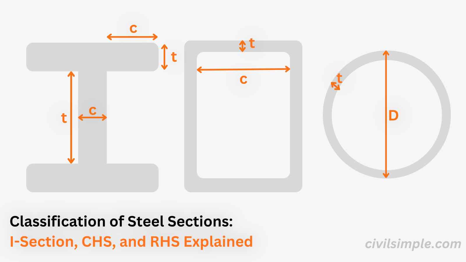
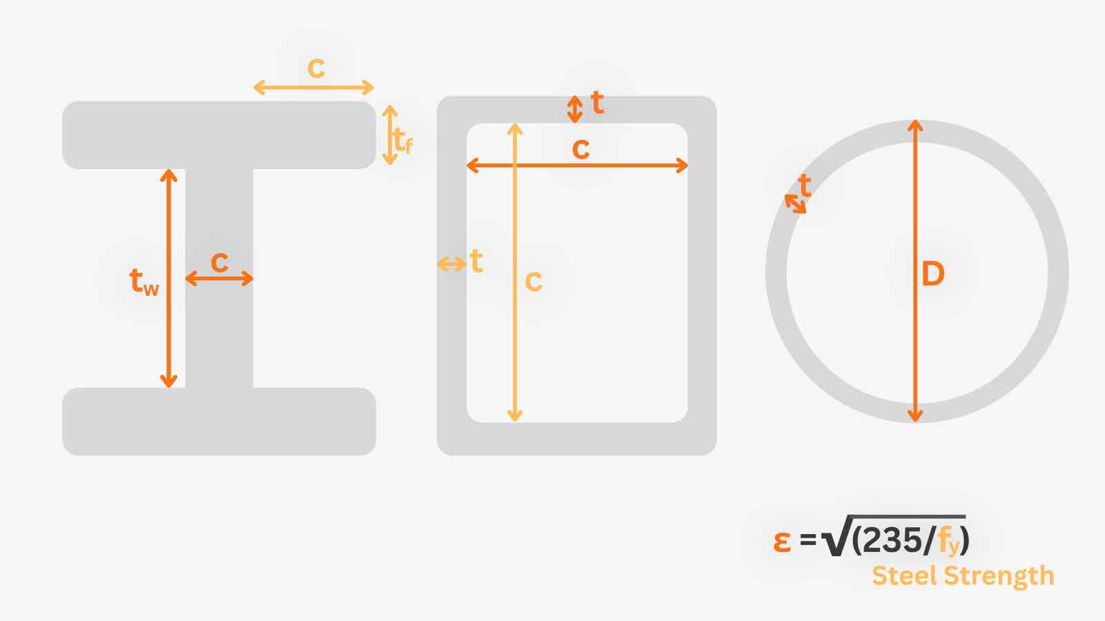
1. Section geometry per plate - As steel section is made of thin plate elements — flanges, webs, or walls, under compression or bending, these thin elements can buckle locally before the whole section reaches yield stress or its full plastic moment capacity.
Width-to-thickness ratio of each plate element is used:
| Element | Ratio Checked |
|---|---|
| I-section outstand flange | |
| I-section web (internal element) | |
| RHS/SHS wall | |
| CHS (whole tube) |
The thinner the element relative to its width, the more slender it is, and the earlier it buckles locally — so the lower its class.
2. The steel grade — expressed through the material factor ε:
3. The stress distribution — pure compression, pure bending, or a combination of bending and axial force (the neutral axis position changes the limits)
4. The boundary conditions — internal elements (restrained on both edges, like a web or RHS wall) can carry more before buckling than outstands (free on one edge, like an I-section flange)
🔢 The Four Classes of Sections (Eurocode 3)
In Eurocode 3, sections are classified into four categories:
Class 1 – Plastic Sections
Can develop a plastic hinge with sufficient rotation capacity
Used in plastic design methods
Width-to-thickness ratios are the smallest (most compact)
Class 2 – Compact Sections
Can reach the full plastic moment capacity
But have limited rotation capacity — cannot sustain a plastic hinge through large rotations
Class 3 – Semi-Compact Sections
Can reach maximum (yield) stress at the extreme fiber
Cannot reach full plastic moment capacity due to local buckling
Design is based on elastic moment capacity
Class 4 – Slender Sections
Local buckling occurs before yield stress is reached
Design must account for effective width/reduced section properties
Common in thin-walled cold-formed sections
Class 1 sections are the most efficient (thick, compact plates)
Class 4 sections are the least efficient (thin, slender plates prone to early buckling).
🔎 Typical Classification Limits (Width-to-Thickness Ratios)
The exact limiting ratios vary slightly from code to code, but the concept is identical. The table below shows the limits from Eurocode 3 (EN 1993-1-1, Table 5.2) for hot-rolled sections; IS 800 (Table 2) follows the same pattern, and AISC uses the compactness limits λp and λr to separate compact, noncompact, and slender elements.
| Element | Class 1 (Plastic) | Class 2 (Compact) | Class 3 (Semi-Compact) |
|---|---|---|---|
| I-section outstand flange (c/t_f) | |||
| Web in pure bending (c/t_w) | |||
| RHS/SHS wall in compression (c/t) | |||
| CHS (D/t) |
If any element's ratio exceeds the Class 3 limit, the section is Class 4 (slender).
🧮 Quick Guideline for Classification of a Section (Step by Step)
Identify the plate elements
For an I-section: the outstand flanges and the web.
For RHS/SHS: the compression wall (flange) and the side walls (webs).
For CHS: the whole tube — a single D/t check.
Identify the plate elements and Calculate the width-to-thickness ratios
Flange (outstand): c/tf
Web: clear depth between flanges, then d/tw
CHS: D/t
Calculate the material factor
ε = (250/fy)0.5
Determine the stress distribution
Pure bending, pure compression, or bending + axial force.
Compare with the code limits
Check each element against the classification limits using material factors and width-to-thickness ratio(Table 5.2 of EN 1993-1-1, or Table 2 of IS 800).
Take the worst class
The section class is the most unfavorable class among its elements — it governs the design method and capacity used.
Work Examples for the section classification can be found in these articles Work Example of Section Classificaiton of I Section, Work Example of Section Classificaiton of CHS and Work Example of Section Classificaiton of RHS
📜 Practical Design Implication
When you classify a section as Class 1 or 2, you can use the full plastic moment capacity (Mplastic) in design.
If it falls into Class 3, you're limited to the elastic moment capacity (Melastic).
If it's Class 4, you must reduce the section properties using effective width methods, which lowers the usable capacity further.
This is why, in real design practice, engineers often prefer compact hot-rolled sections (which are usually Class 1 or 2) over slender built-up or cold-formed sections when plastic design or moment redistribution is required.
📄 Need a section classification check in your design report?
If you want a ready-to-submit design report that includes the classification check with your own steel section, feel free to try our application — what you need is just the design data value, and a ready-to-submit design PDF report will be generated in a minute.

CivilSimple Team
The CivilSimple Team writes practical engineering guides for the profession and the curious. All articles are reviewed for technical accuracy before publication.