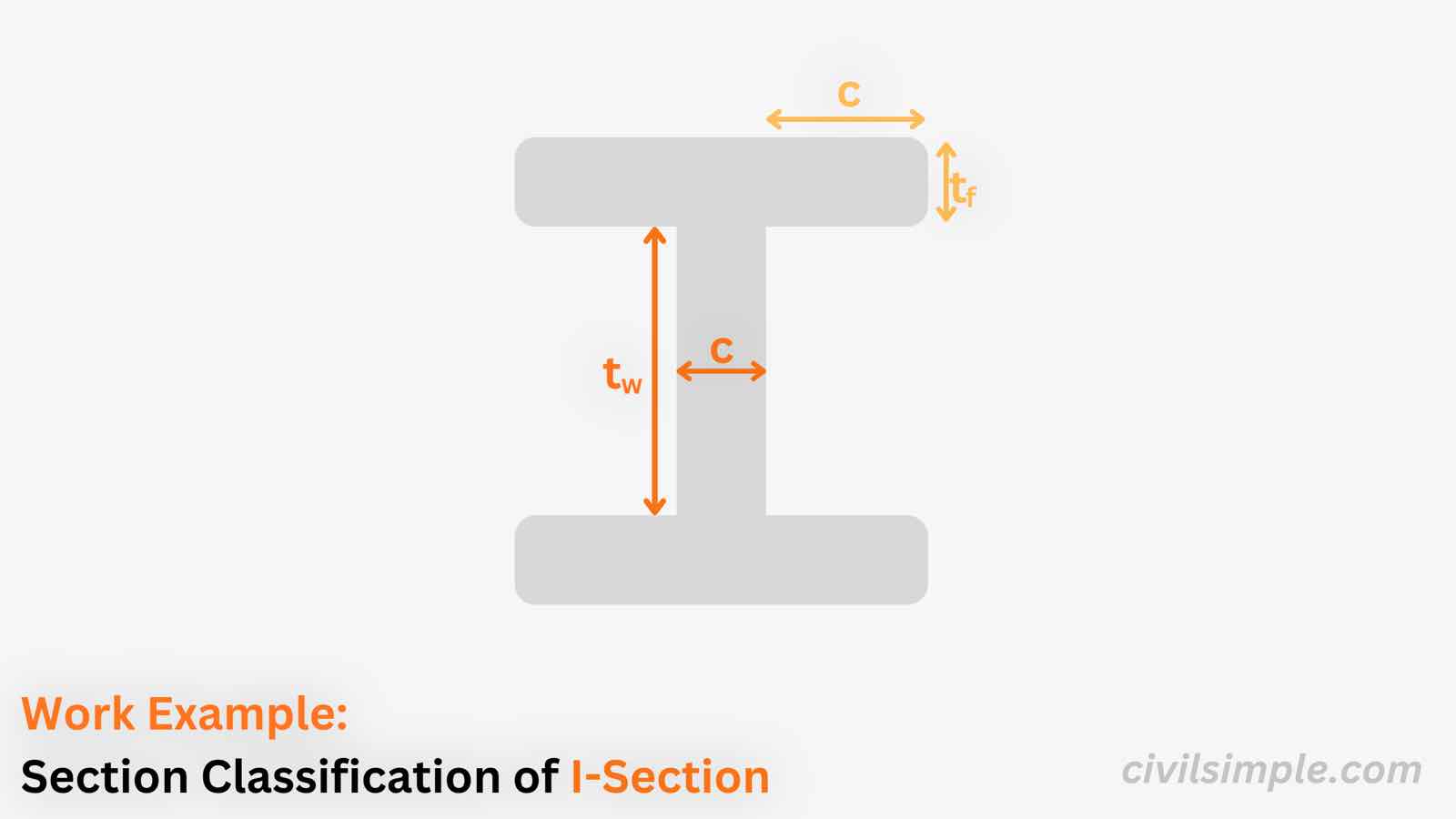
Work Example of Section Classification of I-Section in Bending and Compression
A worked example classifying a hot-rolled I-section (UB) under both pure bending and pure compression — showing how the same section goes from Class 1 (plastic) to Class 4 (slender) as the web limits tighten under uniform compression.
CivilSimple Team
Published Aug 20, 2026
9 min read
Figure 1 — Work Example of Section Classification of I-Section in Bending and Compression
👋 Introduction
Section classification decides how much of a section's strength we are allowed to use in design, and it depends on the stress distribution the section is subject to — not just its geometry. In this article we classify the same I-section (457x191x67) under two stress states:
Pure bending — the web is in bending (compression on one side, tension on the other)
Pure compression — the web is in uniform compression
The flange is in compression in both cases, so its check is unchanged; but the web's limits tighten under uniform compression, which can push the same section into a lower class. As we'll see, this section is Class 1 (plastic) in bending but Class 4 (slender) in compression.
ℹ️ Class Naming Difference between Eurocode 3, IS 800 and AISC
The classification concept is the same worldwide, but the class names and the limiting ratios differ slightly between codes:
Design Capability
Eurocode 3
IS 800
AISC 360
Plastic design (full hinge rotation)
Class 1
Plastic
Compact
Full plastic moment, limited rotation
Class 2
Compact
Compact
Elastic capacity (yield at extreme fibre)
Class 3
Semi-compact
Noncompact
Elastic with reduced (effective) section
Class 4
Slender
Slender
Note that the material factor ε also uses a different constant: EN 1993-1-1 uses ε = √(235/fy), while IS 800 uses ε = √(250/fy).
📐 Design Data
Below are the design information of the I-section (457x191x67), which we will check under both pure bending and pure compression.
Steel Section
Type
I-section
Standard
457x191x67
Breadth, b
190mm
Height, h
453mm
Flange Thickness, tf
12.7mm
Web Thickness, tw
8.5mm
Root Radius, r
10mm
Material
Steel Grade
S355
Yield Strength, fy
355 N/mm²
🔢 Calculation Steps
*Below is using Eurocode symbols and limits Table 5.2, EN 1993-1-1. For IS 800, use ε = √(250/fy) and the limits in its Table 2.
Common checks (geometry & flange)
The flange outstand and web clear depth depend only on the section geometry, and the flange is in compression under both bending and compression — so these checks are the same for both stress states.
The same I-section is Class 1 (plastic) in bending but Class 4 (slender) in compression. Only the web's stress state changed — the geometry is identical. This is why section classification must always be checked against the actual stress distribution, not just the section shape.
📄 Need a Full Design Check Report?
If you want a similar classification check with your own design data, feel free to try our application, what you need is just the design data value, and a ready-to-submit design PDF report will be generated in a minute.
The ready-to-submit PDF Report is not generated by AI but programmed by chartered engineer, which is accurate, no hallucination and same input same output.
The CivilSimple Team writes practical engineering guides for the profession and the curious. All articles are reviewed for technical accuracy before publication.