Work Example: Compression and Buckling Check of an I-Section Column to Eurocode 3
A complete worked example of the compression and flexural buckling check of a 610x305x238 UB column in S355 under 1,000 kN design compression over an 8.0 m buckling length to Eurocode 3 — classification, slenderness, the reduction factor χ and the final utilisation ratio.
CivilSimple Team
Published Oct 5, 2026
10 min read
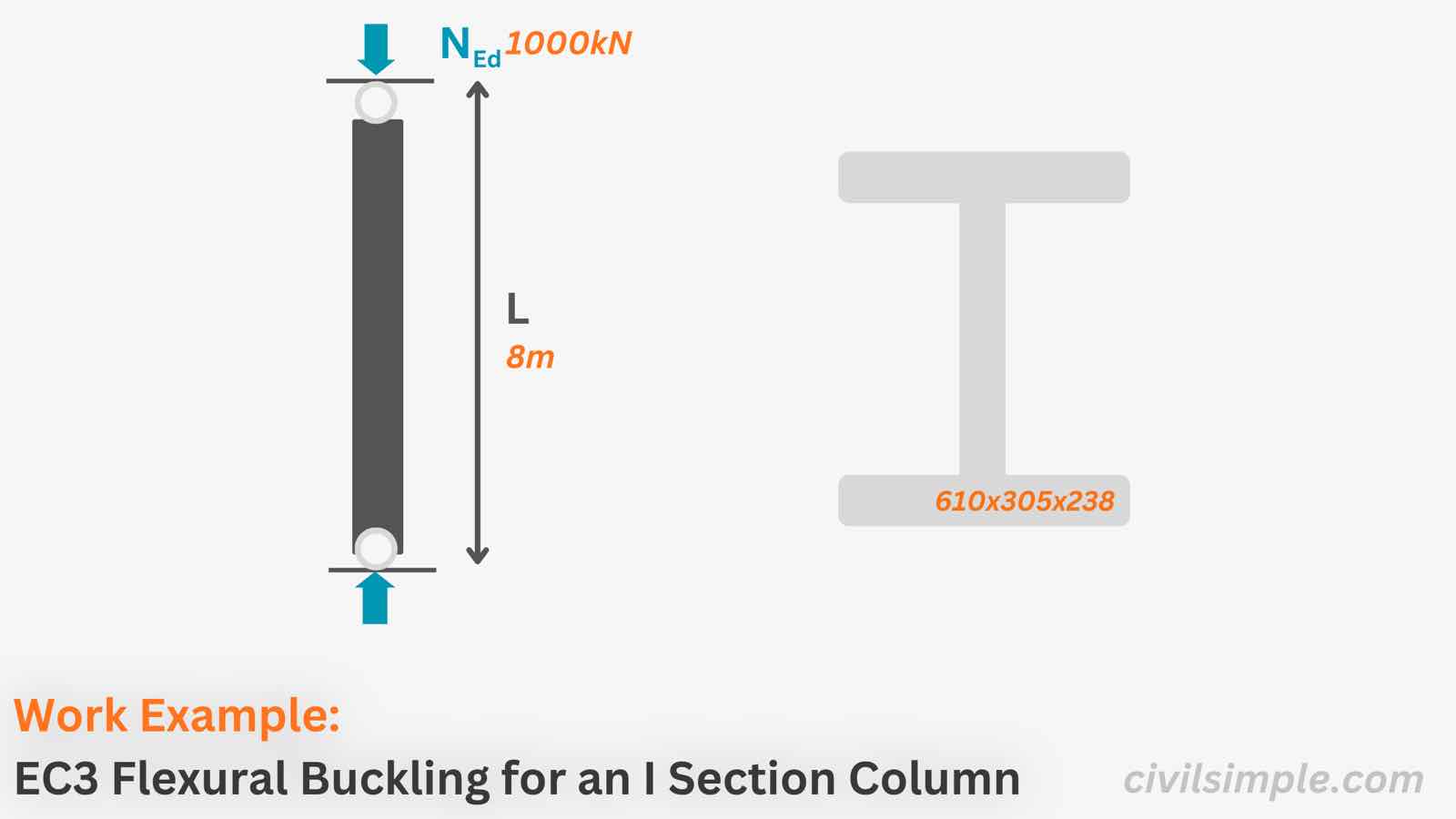
Figure 1 — A worked example to Eurocode 3 — for this slender 8 m column, minor-axis flexural buckling (utilisation 26%) governs well before the cross-section compression capacity (9%) is reached.
👋 Introduction
Steel columns carry axial load, and they can fail by buckling before the steel itself crushes.
In this work example we runs the flexural buckling check of a hot-rolled I-section 610x305x238 UB in S355 carrying a design axial force NEd = 1,000 kN over a buckling length of 8.0 m in both major and minor axis, in the same order a calculation report runs it:
Classify the section — the class decides whether the gross area can be used
Compression check Nc,Rd
Flexural buckling check Nb,Rd about both axes — slenderness, buckling curve and the reduction factor χ, with the lower resistance governing
The buckling lengths are already 8.0 m about both axes (pinned ends, non-sway frame). Following the check order of the flexural buckling guide: elastic critical force → slenderness → buckling curve → χ → Nb,Rd.
3.2.1Elastic critical buckling force Cl.6.3.1.2
Elastic Critical Force, y axis(Cl. 6.3.1.2(1))
=
=
=
Elastic Critical Force, z axis(Cl. 6.3.1.2(1))
=
=
=
3.2.2Non-dimensional slenderness λ̄ Cl.6.3.1.2
Slenderness, y axis(Cl. 6.3.1.2(1))
=
=
=
Slenderness, z axis(Cl. 6.3.1.2(1))
=
=
=
3.2.3Buckling curves Table 6.2
For this hot-rolled I-section:
=
=
From Table 6.2 gives:
- about y-y: buckling curve a, with imperfection factor α = 0.21 from Table 6.1
- about z-z: buckling curve b, with imperfection factor α = 0.34 from Table 6.1
3.2.4Reduction factors Φ and χ Cl.6.3.1.2
Intermediate Factor, y axis(Cl. 6.3.1.2(1))
=
=
=
Reduction Factor, y axis(Cl. 6.3.1.2(1))
=
=
=
Intermediate Factor, z axis(Cl. 6.3.1.2(1))
=
=
=
Reduction Factor, z axis(Cl. 6.3.1.2(1))
=
=
=
∴ The critical reduction factor is χz = 0.36 — minor-axis (z-z) flexural buckling governs.
3.2.5Design buckling resistance and the check Cl.6.3.1.1
∴ The section is sufficient for Flexural Buckling for compression memeber.
📋 Summary
The I Section (610x305x238) is sufficient under Compression (1,000 kN), it :
✓ Pure Compression Check (util: 9%)
✓ Flexural Buckling Check, minor axis z-z (util: 26%)
🙋 Frequently asked questions
1. What is the difference between section compression capacity and buckling capacity?
Section compression capacity (Nc,Rd = 10 800 kN here) is the load the cross-section can carry if the column is stocky and cannot buckle. Buckling capacity is lower for slender columns, because the member can bend sideways before the steel reaches yield. The design capacity is always the buckling capacity (Nb,Rd = 3 896 kN here) — never more than the section capacity.
2. Which axis governs buckling in an I-section column?
Usually the minor (weak) axis z-z, because the radius of gyration is smaller and the slenderness is higher — here λ̄z = 1.45 against λ̄y = 0.40. If the column is braced about the minor axis at intermediate points, the major axis can govern instead, so always check both axes and take the lower resistance.
3. How do I determine the effective (buckling) length of a steel column?
Effective length is the actual length multiplied by a factor that depends on the end restraint: a column pinned at both ends has Lcr equal to its actual length, fixed ends reduce it, and a free end increases it. In real frames, take the values agreed in the frame analysis — the buckling overview article shows how end conditions translate into buckling lengths.
4. Why does section classification matter in a compression check?
Classification tells you whether the flanges and web are stocky enough to reach full yield without local buckling. This section is Class 2 in compression, so the gross area applies. A Class 4 section must use a reduced effective area Aeff, which lowers the compression capacity.
5. Can I use this example for other I-sections?
Yes. The method is the same for any I-section — the step-by-step guide collects the formulas. Change the section properties, steel grade, buckling length and load, pick the buckling curve from Table 6.2, and repeat the steps: the chain Lcr → λ̄ → curve → χ → Nb,Rd stays identical.
📄 Need a Column Buckling Check in Your Design Report?
If you want a ready-to-submit design report with the buckling check, section classification and the full cross-section checkin Eurocode 3, feel free to try our application — what you need is just the design data values, and a ready-to-submit PDF report will be generated in a minute.
The ready-to-submit PDF Report is not generated by AI but programmed by chartered engineer, which is accurate, no hallucination and same input same output.
Eurocode 3: Design of steel structures — Part 1-1: General rules and rules for buildings (EN 1993-1-1)—CEN (European Committee for Standardization)·2005
CivilSimple Team
The CivilSimple Team writes practical engineering guides for the profession and the curious. All articles are reviewed for technical accuracy before publication.