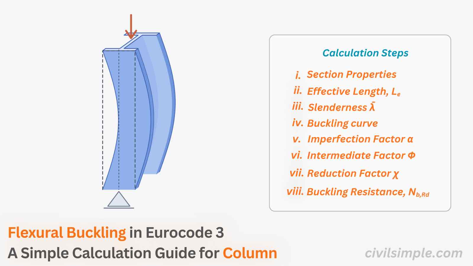
Previously, we discussed about what buckling is and why slender members fail long before the steel itself yields.
This article is mainly focus on how to implement checking of one of the buckling mode - Flexural Buckling for Compression Memeber based on Cl.6.3.1 in Eurocode 3 (EN 1993-1-1).
❓ What is flexural buckling?
Flexural buckling is the most common buckling mode for columns. A straight member under axial compression suddenly bows sideways, like a plastic ruler pressed from both ends.It can occur at a load well below what the cross-section could carry in pure compression (yielding).
Because buckling is a form of structural failure, it is important to check the member's buckling resistance, not just the strength of its cross-section.
Other modes exist, such as torsional buckling and lateral-torsional buckling, details can found in another article. For common doubly symmetric sections (I, H and hollow sections), flexural buckling is usually the one that governs.
Major axis vs. minor axis
Every cross-section has two principal axes, and a column can bow about either one.
- Major axis (y-y): the strong axis, with the larger I. For an I-section it runs through the web horizontally, and bending about it uses the flanges most effectively.
- Minor axis (z-z): the weak axis, with the smaller I. It runs vertically through the web.
Because I-section is smaller about the minor axis, a column usually buckles about z-z first unless it is braced in that direction. Normally, we must check both axes and take the lower resistance.
💡 The Idea Behind the Calculation
The flexural buckling check in Eurocode 3 determines how much of a column's full compressive capacity remains available once the effects of buckling are taken into account.
This capacity depends on four main factors:
- Buckling length (Lcr): how long the column is, and how its ends are restrained.
- Section geometry: the area (A) and the radius of gyration (i), which show how efficiently the shape resists bending.
- Material: the steel's stiffness (E) and its yield strength (fy).
- Imperfections (α): real columns are never perfectly straight and carry residual stresses from rolling or welding. This depends on the section type and how it was made (which buckling curve to be used).
Then, these factors are converted into two dimensionless factors:
- Non-dimensional slenderness ( ): combining Length, geometry, stiffness and strength
- Reduction factor (χ): combining buckling curve and its imperfection factor (α) and .
The reduction factor is applied to the section's axial capacity to get the design buckling resistance (Nb,Rd). This is then compared with the design axial force (NEd):
📖 Glossary: parameters in the buckling resistance calculation
As many parameters are involved in the calculation, the glossary below lists each one with a short explanation. The step-by-step calculation guide follows right after it.
Common Glossary for Buckling Resistance Calculation
| Symbol | Name | Simple meaning |
|---|---|---|
| NEd | Design axial compression force | The factored load the column must carry |
| Nb,Rd | Design buckling resistance | The maximum compression the column can safely resist, considering buckling |
| Ncr | Elastic critical buckling force | The theoretical load at which a perfect column would buckle |
| A | Gross cross-sectional area | Area of the section (use Aeff for Class 4) |
| Aeff | Effective area | Reduced area for slender (Class 4) sections |
| fy | Yield strength | Steel strength, e.g. 275 or 355 MPa |
| E | Young's modulus | Steel stiffness, 210,000 MPa |
| I | Second moment of area | Bending stiffness of the section about an axis |
| i | Radius of gyration | i = √(I/A): how efficiently the section resists buckling |
| L | System length | Actual length of the column between supports |
| Lcr | Buckling length | Effective length = k × L, depending on end restraints |
| λ̄ | Non-dimensional slenderness | How slender the column is, relative to its yield limit |
| λ1 | Reference slenderness | 93.9ε — the slenderness at which buckling and yielding coincide |
| ε | Steel grade factor | ε = √(235/fy) |
| α | Imperfection factor | Accounts for real-world imperfections and residual stresses |
| Φ | Intermediate factor | Helper value used to calculate χ |
| χ | Reduction factor | Between 0 and 1: the fraction of the full section capacity left after buckling |
| γM1 | Partial safety factor | 1.0 as recommended — check your National Annex |
| Buckling curve | a0, a, b, c, d | Picks α based on section type, steel grade and axis |
📍 Quick Calculation Guideline for Flexural Buckling Check
Given a section with an applied Compression NEd and its effective length, determine whether it pass Flexural Buckling Check
Get the design load and section properties
Collect NEd, the section properties (A, Iy, Iz) and fy.
Confirm the section is Class 1–3; a Class 4 section uses its effective area Aeff.
Determine the buckling length Lcr, for each axis
Lcr = k × L
k depends on how the ends are held, refer to table below.
| End conditions (bottom / top) | k |
|---|---|
| Pinned / pinned | 1.0 |
| Fixed / pinned | 0.7 |
| Fixed / fixed | 0.5 |
| Fixed / free (cantilever) | 2.0 |
Calculate the non-dimensional slenderness λ̄
λ̄ = (Lcr / i) / λ1
i = √(I/A); λ1 = 93.9ε; ε = √(235/fy); carry out for both axes.
For λ̄ ≤ 0.2, or NEd/Ncr ≤ 0.04, buckling can be ignored and only the cross-section check is needed.
Select the buckling curve and imperfection factor α
Use EN 1993-1-1 Table 6.2 to choose one of the buckling curves a0, a, b, c, d, based on the section shape, way of form(rolled, welded, hollow), the height-to-width ratio h/b, the flange thickness, the steel grade and the buckling axis.
For each buckling curve can be used to obtain to the imperfection factor α in EN 1993-1-1 Table 6.2, where a0 = 0.13, a = 0.21, b = 0.34, c = 0.49, d = 0.76.
| Curve | a0 | a | b | c | d |
|---|---|---|---|---|---|
| α | 0.13 | 0.21 | 0.34 | 0.49 | 0.76 |
Calculate Φ and the reduction factor χ
Φ = 0.5 [ 1 + α (λ̄ − 0.2) + λ̄² ]
χ = 1 / ( Φ + √(Φ² − λ̄²) ), where χ ≤ 1.0.
A thcik column gets χ close to 1.0; a slender column far less.
Calculate the buckling resistance Nb,Rd
Nb,Rd = χ · A · fy / γM1 (Class 1–3), = χ · Aeff · fy / γM1%% (Class 4)
γM1 = 1.0 as recommended.
Compare and conclude
Repeat Steps 3–6 for both axes, take the lower Nb,Rd and run the check:
NEd / Nb,Rd ≤ 1.0
⚠️ Common mistakes to avoid
- Checking only the major axis and forgetting the minor axis
- Using the wrong buckling length — assuming "fixed" ends where the connections are really pinned
- Picking the wrong buckling curve — h/b and flange thickness matter (Table 6.2)
- Forgetting the γM1 value in your National Annex
- Skipping the section classification — a Class 4 section must use Aeff
🙋 Frequently asked questions
1. What is flexural buckling in Eurocode 3?
Flexural buckling is a stability failure where a column under axial compression suddenly bends sideways. Eurocode 3 (EN 1993-1-1, clause 6.3.1) checks it by reducing the section's full compressive capacity with a reduction factor χ, which depends on the column's slenderness and its imperfections.
2. Which axis governs column buckling, major or minor?
Usually the minor axis (z-z), because the second moment of area is smaller about it, so the column bends there more easily. You should still check both axes and use the lower buckling resistance — especially if bracing differs in each direction.
3. What is the reduction factor χ in Eurocode 3?
χ is a value between 0 and 1 that reduces the cross-section resistance to account for buckling. A stocky column has χ close to 1.0, while a slender column has a much lower value. It is calculated from the slenderness λ̄ and the imperfection factor α of the selected buckling curve.
4. How do I choose the buckling curve (a0, a, b, c, d)?
Use EN 1993-1-1 Table 6.2. The curve depends on the section type (rolled, welded, hollow), the height-to-width ratio and flange thickness, the steel grade and the buckling axis. Each curve gives an imperfection factor α: 0.13 (a0), 0.21 (a), 0.34 (b), 0.49 (c) and 0.76 (d).
5. When can I ignore flexural buckling?
Buckling effects can be neglected when the non-dimensional slenderness λ̄ ≤ 0.2, or when NEd/Ncr ≤ 0.04. In these cases only the cross-section resistance check is needed.
6. What buckling length should I use for a column?
The buckling length is Lcr = k × L, where k depends on the end restraints: for example k = 1.0 for pinned–pinned, 0.7 for fixed–pinned, 0.5 for fixed–fixed and 2.0 for a cantilever. In real frames, use the values consistent with your structural model and Eurocode guidance.
7. What value of γM1 should I use for buckling checks?
EN 1993-1-1 recommends γM1 = 1.0 for member stability checks, but the value is set in each country's National Annex. Always confirm the value for the country where the project is located.
📋 Key takeaways
- Flexural buckling is the sideways bowing of a compression member — and it usually happens about the minor axis.
- Eurocode 3 handles it with a reduction factor χ based on slenderness and imperfections.
- The workflow is: Lcr → λ̄ → curve and α → Φ → χ → Nb,Rd → check.
- Always check both axes and use the lower resistance.
📄 Need a column buckling check in your design report?
Buckling decides how much of your column's capacity you are allowed to use. If you want a ready-to-submit design report with the buckling check, section classification and the full cross-section check in Eurocode 3, feel free to try our application — what you need is just the design data values, and a ready-to-submit PDF report will be generated in a minute.
References
- Eurocode 3: Design of steel structures — Part 1-1: General rules and rules for buildings (EN 1993-1-1) — ·2005

CivilSimple Team
The CivilSimple Team writes practical engineering guides for the profession and the curious. All articles are reviewed for technical accuracy before publication.