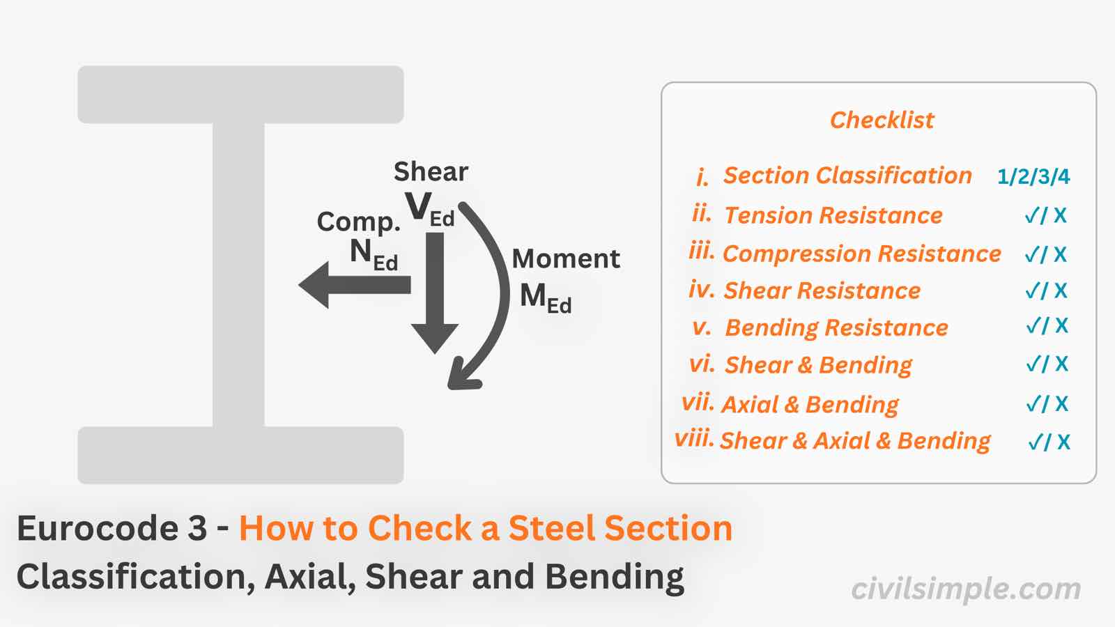
Breif guide of resistance of cross-section
To check if a steel member is structurally sufficient under certain axial force, moment and shear, a cross-section resistance check is required. In the article below, it provide a simple guide according to Eurocode 3 EN 1993-1-1:2005:
- Section Classification
- Axial Force Check [Tension and Compression]
- Bending Resistance [Major and Minor Axis]
- Shear Resistance
- Combine Check [Bending and Shear, Bending and Axial Force and Bending, shear and axial force]
Please noticed that above check is for steel cross-section resistance under fully-restrained member. For un-restrained member, buckling effect need to be considered, which will discuss in another article.
Step 0: Gather Input
To design a steel section, there are three basic information you need to know:
- Section Geometry (I section/RHS/CHS)
- Steel Material Strength (fy)
- Design Action (Shear/Moment/Axial Load of the section)
Step 1: Section Classification
Here will based on the section geometry and the corresponding material strength, classify the corresponding Class (Class 1, 2, 3 or 4) subject to three checking conditions: Cl.5.5, EN 1993-1-1:2005
- Compression
- Bending
- Compression and Bending
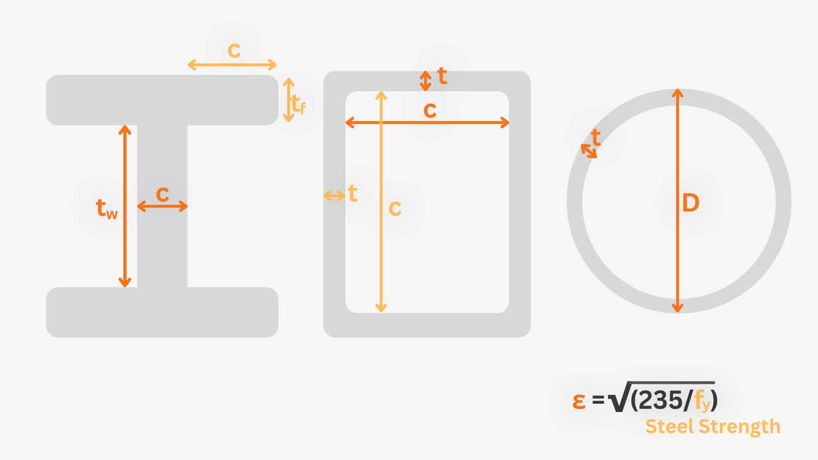
The details explanation and example of section classification can refer to other articles.
Step 2: Axial Resistance
For section under axial force, either tension or compression. Axial resistance check need to be carry out.
Step 2.1: Tension Resistance
The tension resistance of a steel section can be determined by:
fy = Strength (N/mm2)
A = Gross Area (mm2)
γM0 = Material Factor = 1.0 from eurocode 3
NEd = Design Axial Force
Step 2.2: Compression Resistance
The compression resistance of a steel section is similar to tension resistance for Class 1 - 3 Section, but an effective area will be used for Class 4, as shown below:
Aeff = Effective Area (mm2)
Step 3: Bending Resistance
For section with bending moment, either moment at major axis (y-axis) and/or minor axis (z-axis).
To carry out the capacity, it need to refer to the class subject to bending from section classification:
If both moment at major and minor axis exist for the section, combination of resistance check need to used as below.
Step 4: Shear Resistance
The shear resistance of a steel section is determined by below, without any need of section classification:
Av = Shear Area
| Section | Shear area Av |
|---|---|
| Rolled I/H section — load parallel to web | |
| RHS — load parallel to depth h | |
| RHS — load parallel to width b | |
| CHS — any direction |
Step 5: Combine Check
As axial force, moment and shear force may be applied to same cross-section at the same time, so other than simple separate resistance check, we also need to carry out the combine check.
Step 5.1: Bending and Shear Check
Combine Bending and Shear Check
1. Check the shear force to shear resistance ratio,Step 5.2: Bending and Axial Check
When the section is under bending and axial, below check need to perform based on the Class subject to compression and bending:
Class 1 and 2 - I section - Specific Axis (y/z) Bending and Axial Force Check
1. Check Condition to determine if the bending resistance of specifc axis need to apply reduction
n = NEd/Npl,Rd
a = (A - 2btf)/A
By comparing , it can determined if the section is sufficient with the combine design action.
Class 1 and 2 - RHS/CHS - Specific Axis (y/z) Bending and Axial Force Check
For RHS or CHS, a reduction factor from axial need to apply to the Bending resistance Mpl,Rd, the reduced resistance can be found in below:
n = NEd/Npl,Rd
aw = (A - 2bt)/A ≤ 0.5
af = (A - 2bt)/A ≤ 0.5
By comparing , it can determined if the section is sufficient with the combine design action.
Class 1 and 2 - RHS/CHS/I section - Biaxial Bending and Axial Force Check
For RHS or CHS or I section, where biaxial bending (My & Mz) and axial force NEd exist, first determined the section's corresponding MN,y,Rd and MN,z,Rd, and carry out check as below:
α = 2 ,β = 5n ≥ 1 for I section
α = 2 , β = 2 for CHS
α = β = 1.66/(1 - 1.13n2) ≤ 6 for RHS
Class 3 - RHS/CHS/I section - Specific Axis (y/z) or Biaxial Bending and Axial Force Check
For section subject to bending and compression classified as Class 3,Nc,Rd = 2 ,β = 5n ≥ 1 for I section
Step 5.3: Bending, Shear and Axial Force Check
For section under bending, shear and axial force at the same time, it will:
-
Determine the shear force to resistance ratio and shear reduction factor required, refer to Step 5.1 - Bending and Shear Check.
-
If , replace fy to and carry out checking according to Step 5.2 - Bending and Axial Check.
📝Wrap Up and Summary
To check if a steel section is adequate, above is a quick guideline for different combination of design action and sections:
- Section Classification
- Axial Force Check [Tension and Compression]
- Bending Resistance [Major and Minor Axis]
- Shear Resistance
- Combine Check [Bending and Shear, Bending and Axial Force and Bending, shear and axial force]
Further work examples will be providing in other articles.
Again, please noticed that above steel cross-section check are for fully-restrained member where no buckling effect need to be considered. For un-restrained member, buckling effect need to be considered, which will discuss in another article.
📄 Want a ready-to-submit steel design report?
If you want a ready-to-submit design report that runs the section resistance and capacity check with your own steel section, feel free to try our application — you just enter the design data, and a ready-to-submit PDF report is generated in a minute.
References
- Eurocode 3: Design of steel structures — Part 1-1: General rules and rules for buildings (EN 1993-1-1) — ·2005
- DESIGNERS’ GUIDE TO EN 1993-1-1 EUROCODE 3: DESIGN OF STEEL STRUCTURES — ·2005

CivilSimple Team
The CivilSimple Team writes practical engineering guides for the profession and the curious. All articles are reviewed for technical accuracy before publication.