What Is Buckling in Steel? — Types, Causes and Effective Length
Simple Guide about what buckling in steel is, why slender members fail suddenly, the five types of buckling, effective length, factors affecting critical buckling load and ways to reduce it.
CivilSimple Team
Published Sep 28, 2026
15 min read
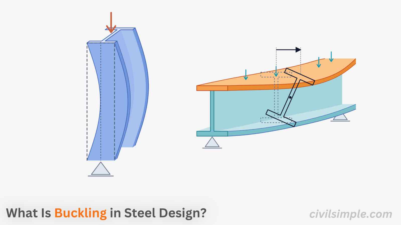
Figure 1 — Buckling in steel — a slender compression member suddenly loses its straight shape long before the material yields.
🤔 Why Does Buckling Matter?
In steel design, a member can fail in two different ways: strength failure or stability failure.
A strength failure occurs when the steel reaches its strength limit. But a slender steel member can become unstable and buckle before the steel itself reaches its yield strength.
This is particularly important for columns, struts, braces, and slender beams subjected to compression or bending. Therefore, checking stability is an essential part of steel design.
A real-world example - buckling failure:
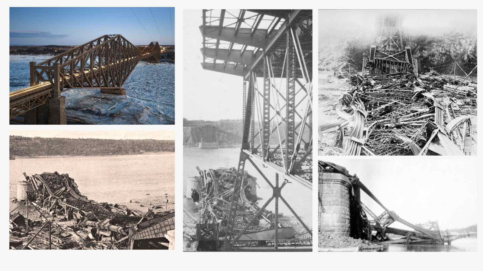
The importance of buckling can be seen in the Quebec Bridge collapse of 1907, where the failure of compression members contributed to the progressive collapse of the bridge.
The key lesson is: a steel member does not always need to reach its material strength to fail. It can fail because it becomes unstable.
❓ What is buckling in steel?
Buckling is the sudden sideways deflection of a slender member under compression caused by instability rather than by the material running out of strength.
Think of pressing down on a plastic ruler. At first, the ruler stays straight as you increase the load. But after reaching a certain load, it suddenly bends sideways.The ruler has not necessarily broken because its material has reached its strength. Instead, it has lost stability.
A slender steel member can behave in a similar way.
Strength failure vs. buckling
There are two different failure mechanisms to understand:
Strength failure (crushing): the stress in the steel reaches its resistance. This is more likely to govern for short, stocky members.
Stability failure (buckling): the member becomes unstable and deflects sideways before the steel reaches its yield strength. This is more likely to govern for long, slender members.
To determine whether a compression member will fail by buckling or by material strength, an important variable — the critical load — was introduced in the 18th century.
🔑 Key Concept: Euler's Critical load
In the 18th century, Leonhard Euler worked out the load at which an ideal, perfectly straight column becomes unstable:
Euler's critical load
where Ncr = the critical (buckling) load E = the stiffness of the material. (normally take 210,000 N/mm² for steel) I = the second moment of area, which measures how well the cross-section resists bending L= the actual member length K= the effective length factor, which accounts for how the ends are held
🏗️ The five types of buckling in steel members
Buckling is not just one phenomenon. Depending on the shape of the member and how it is loaded, a steel member can lose stability in five common ways.
1. Flexural buckling
The column bends sideways about its weak axis, which is the direction in which the section is least stiff. This is the classic column buckling case and the one Euler's formula describes. It is the most common mode in columns, struts and braces.
2. Torsional buckling
The column twists about its length without bending sideway. It is mainly a concern for open sections with low torsional stiffness, such as cruciform (cross-shaped) sections.
3. Flexural-torsional buckling
Above buckling mode (bending and twisting) happen at the same time. This is typical for singly symmetric or asymmetric open sections such as angles, tees and channels, where the shear center and the centroid do not coincide.
4. Lateral-torsional buckling
In a beam, the top flange is in compression and behaves like a long, thin column. If the beam is not restrained sideways, the compression flange moves out and the section twists. Deep, narrow, unrestrained I-beams are the most at risk.
5. Local buckling
Individual plate elements — a thin flange or web — can buckle before the member as a whole does. Whether this happens is governed by the width-to-thickness ratio of each element, which is exactly what section classification checks: a Class 4 section must be reduced to its effective area.
Summary of the types of buckling
Buckling mode
Where you'll see it
Think of it as
What controls it
Flexural
Columns, struts, braces
Bowing
Length, end restraint, weak-axis stiffness
Torsional
Cruciform and other open sections
Twisting
Torsional stiffness, restraint against twist
Flexural-torsional
Angles, tees, channels
Bowing plus twisting
Section shape, restraint
Lateral-torsional
Unrestrained beams
Beam flopping sideways
Spacing of lateral restraints
Local
Thin flanges and webs
Plate rippling
Width-to-thickness ratios
🧩 What is the factors affecting the buckling?
The more slender a member is, the more sensitive it becomes to stability. Its behaviour depends not only on the strength of the steel, but also on factors such as:
⬆️ member length or slenderness → ⬆️ Buckling risk
⬆️ Initial imperfections or residual stresses → ⬆️ Buckling risk
📏 Key Concept: Effective length
The effective length Lcr is the length of an equivalent pinned-pinned column that would buckle at the same load as the real member.
Two columns can have the same section and the same actual length yet very different buckling loads. What changes is how their ends are held:
Effective length
L is the real length; K is the effective length factor, set by how well each end is held against sideways movement and rotation. Ends well held → small K → higher buckling load. Ends poorly held → large K → lower buckling load.
Effective length factors for common end conditions
End conditions (bottom / top)
Theoretical K
Recommended design K*
Pinned / pinned
1.0
1.0
Fixed / fixed
0.5
0.65
Fixed / pinned
0.7
0.80
Fixed / free (cantilever)
2.0
2.1
Fixed base, rotation fixed but free to sway
1.0
1.2
Pinned base, rotation fixed but free to sway
2.0
2.0
* Recommended values follow the AISC 360 Commentary (Table C-A-7.1) — more conservative than theory because real connections are never perfectly fixed. Eurocode 3 does not tabulate K the same way: it takes the buckling length from the actual restraint and frame behaviour, so always check the code you are designing to.
Braced and sway frames
Braced (non-sway) frames: bracing or shear walls stop sideways movement, so columns usually get K of 1.0 or less.
Unbraced (sway) frames: the frame relies on its own stiffness and can sway, so K is usually greater than 1.0 — these columns are much more vulnerable to buckling.
Worked example — the same 4 m column, different ends
Take a steel column with L = 4 m and compare two end conditions:
A
Case A — pinned-pinned
K = 1.0 ⇒ Lcr = 1.0 × 4.0 = 4.0 m
Both ends held against sideways movement but free to rotate — the reference case.
B
Case B — fixed-free (cantilever)
K = 2.0 ⇒ Lcr = 2.0 × 4.0 = 8.0 m
Fixed at the base, completely free at the top — the worst case.
🛡️ How to reduce buckling risk
Therefore, to reduce the buckling effect to a steel structural, below :
Brace to shorten the unbraced length. Bracing a column at mid-height halves Lcr — which multiplies the buckling load by four.
Restrain the weak axis. Flexural buckling usually happens about the weak axis, so brace the direction in which the section is least stiff.
Choose sections with a large radius of gyration — hollow sections and well-balanced shapes put more area away from the centroid.
Don't assume perfect fixity. Real connections are rarely fully rigid, so use conservative K values.
Restrain the compression flange of beams to control lateral-torsional buckling.
🙋 Frequently asked questions
1. What is the difference between buckling and yielding?
Yielding is a material failure: the stress reaches the yield point and the steel deforms permanently. Buckling is a stability failure: the member suddenly bows or twists, often before the yield stress is reached anywhere.
2. Is buckling the same as bending?
No. Bending is a steady, predictable response to a transverse load. Buckling is a sudden change of shap that happens when compression makes a member unstable.
3. Why do long columns fail at lower loads than short ones?
The buckling critical load decreases with the square of the effective length — double the length, and the buckling critical load drops to one quarter. Slender columns can become unstable long before the steel reaches its yield strength.
4. What is the effective length factor K?
K converts the real member length into the length of an equivalent pinned-pinned column. Well-restrained ends give a small K; poorly restrained or free ends give a large K.
5. Which steel sections are most prone to buckling?
Long members with a low radius of gyration; sections with thin plate elements (local buckling); open sections such as angles and tees (torsional modes); and deep, unrestrained beams (lateral-torsional buckling).
6. How can buckling be prevented?
Shorten the unbraced length with bracing, restrain the weak axis and compression flanges, choose sections with a large radius of gyration, and design connections with realistic — conservative — end restraint.
📋 Key takeaways
Buckling is a stability failure, not a strength failure.
There are 5 modes of buckling, which are flexural buckling, torsional buckling, flexural-torsional buckling, lateral-torsional buckling and local buckling.
Euler's Critical load Ncr = (π2EI)/(Lcr)2 defines elastic critical load at which buckling occurs.
The effective length is determined based on the member length and its restraint conditions. It is an important factor in calculating the elastic critical load.
To reduce the risk of buckling, bracing can be added, sections with a larger radius of gyration can be selected, and the restraint conditions can be modified.
📄 Need a steel section check in your design report?
Buckling decides which part of your section you are allowed to use. If you want a ready-to-submit design report that runs the classification and the full cross-section check with your own I-section, CHS or RHS in eurocode 3, feel free to try our application — what you need is just the design data values, and a ready-to-submit PDF report will be generated in a minute.
The ready-to-submit PDF Report is not generated by AI but programmed by chartered engineer, which is accurate, no hallucination and same input same output.
Eurocode 3: Design of steel structures — Part 1-1: General rules and rules for buildings (EN 1993-1-1)—CEN (European Committee for Standardization)·2005
CivilSimple Team
The CivilSimple Team writes practical engineering guides for the profession and the curious. All articles are reviewed for technical accuracy before publication.