Work Example: Combined Compression and Bending Buckling Check of an I-Section Beam-Column to Eurocode 3
A complete worked example of the combined compression and bending buckling check of a 610x305x238 UB beam-column in S355 under 800 kN compression and 800 kNm + 100 kNm biaxial bending to Eurocode 3 — classification, cross-section checks, buckling reduction factors and the interaction equations 6.61 and 6.62.
CivilSimple Team
Published Oct 6, 2026
12 min read
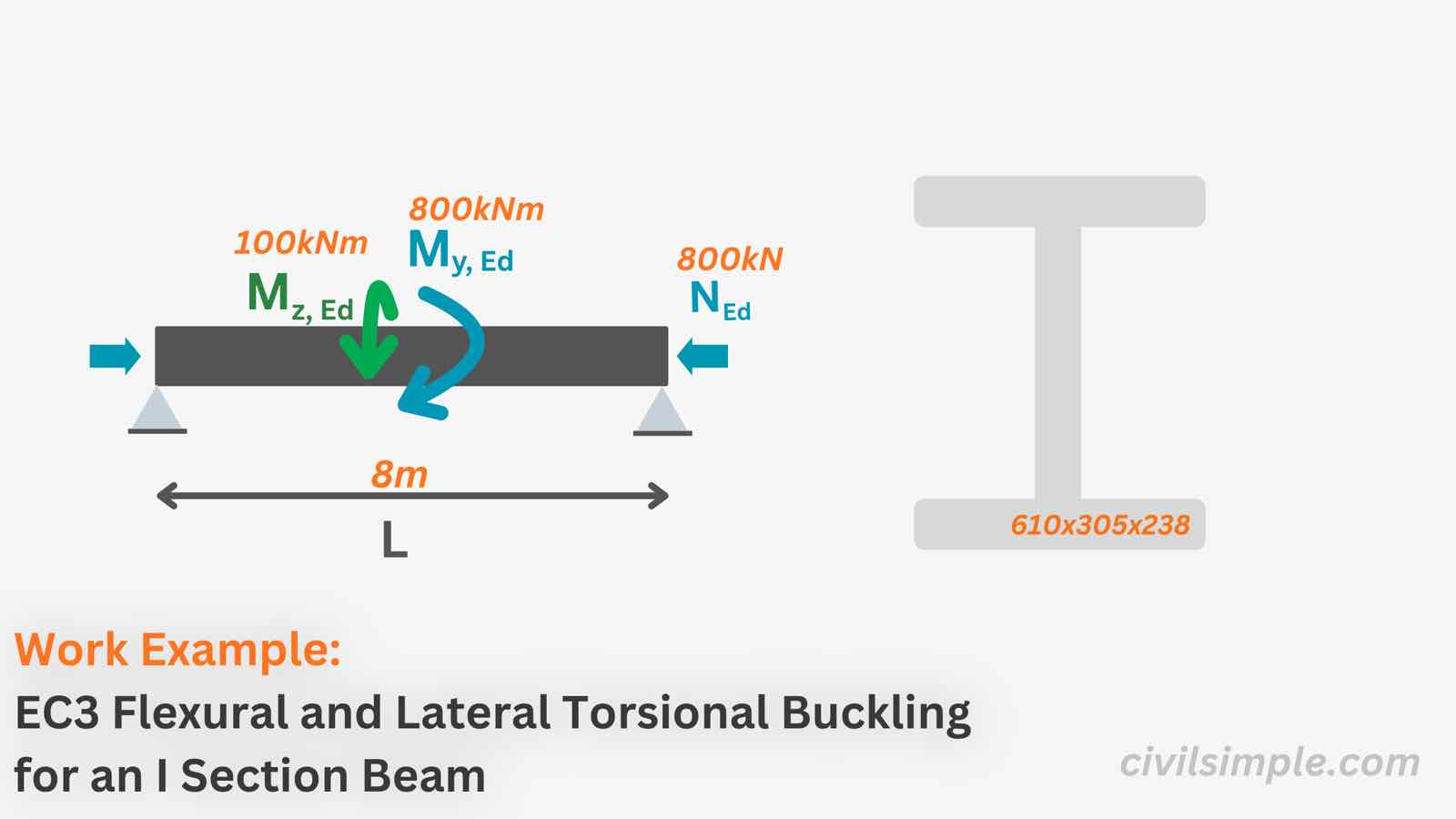
Figure 1 — A worked example to Eurocode 3 — under 800 kN compression with biaxial bending, the minor-axis interaction equation 6.62 governs with a utilisation of 92%.
👋 Introduction
A beam-column carries axial compression and bending at the same time, and the two make each other worse: the bending bows the member, and the compression acts on that bow.
This work example runs the full check of a hot-rolled I-section 610x305x238 UB in S355 under NEd = 800 kN, My,Ed = 800 kNm and Mz,Ed = 100 kNm over an 8.0 m buckling length, in the order a calculation report runs it:
Classify the section
Cross-section checks — compression, bending about both axes, and the biaxial + axial check
Member buckling checks — flexural buckling (χy, χz) and lateral-torsional buckling (χLT)
Interaction check — Eq. 6.61 and 6.62 with the Annex B interaction factors, the governing step
Modification Factor for moment distribution(Cl. 6.3.2.3(2))
=
=
=
Reduction Factor with moment distribution considered(Cl. 6.3.2.3(2), Eq. 6.58)
=
=
=
Design Buckling Resistance Moment(Eq. 6.55)
=
=
=
Buckling Check under bending(Cl. 6.3.2.1(1), Eq. 6.54)
=
=
=
∴ The section is sufficient for Lateral-Torsional Buckling
4.3Interaction check — bending and axial compression Cl.6.3.3
In below analysis, calculation of interactive factors kyy, kyz, kzy, kzz is using alternative method B as stated in Annex B of EC3.
For moment distrubtion factor from Table B3,
=
For capacity of section subject to axial and bending from Table 6.7,
=
=
=
=
=
Interaction Factor, kyy(Table B.1)
=
=
=
Interaction Factor, kzy(Table B.2)
=
=
=
Interaction Factor, kzz(Table B.1)
=
=
=
Interaction Factor, kyz(Table B.1)
=
=
=
Combined Buckling Check, major axis(Cl. 6.3.3, Eq. 6.61)
=
=
=
Combined Buckling Check, minor axis(Cl. 6.3.3, Eq. 6.62)
=
=
=
∴ The section is sufficient for Bending and Axial Compression Buckling — the governing check is Eq. 6.62 about the minor axis
📋 Summary
The I Section (610x305x238) is sufficient under Compression (800 kN), Moment at Major Axis (800 kNm) and Moment at Minor Axis (100 kNm):
Cross-Section Resistance
✓ Pure Compression Check (max util: 7%)
✓ Bending Check at major axis (max util: 30%)
✓ Bending Check at minor axis (max util: 18%)
✓ Bending and Axial at major axis is pass due to no reduction factor from axial
✓ Bending and Axial at minor axis is pass due to no reduction factor from axial.
✓ Biaxial Bending Moment and Axial (util: 27%)
Buckling Resistance
✓ Buckling Resistance under axial compression (util: 21%)
✓ Buckling Resistance under bending (util: 50%)
✓ Combined Axial & Bending Ratio (Eq. 6.61) (util: 72%)
✓ Combined Axial & Bending Ratio (Eq. 6.62) (util: 92%)
🙋 Frequently asked questions
1. What is the combined compression and bending check in Eurocode 3?
It is the stability check for a beam-column — a member carrying axial compression and bending at the same time. Clause 6.3.3 checks it with the two interaction equations 6.61 and 6.62, each adding an axial term and two bending terms weighted by the interaction factors k. The guide article explains every parameter.
2. Why can't compression and bending be checked separately?
Because compression and bending make each other worse: bending bows the member, and the compression acts on that bow, adding second-order moment. The interaction equations capture this amplification through the k factors — adding two separate utilisation ratios would miss it.
3. What are the interaction factors kyy, kyz, kzy and kzz?
They weight the bending terms in the interaction equations for second-order effects and the coupling between axes. This example uses Annex B (Method 2) — Tables B.1 and B.2 give ready-made formulae, and Table B.3 gives the moment-distribution factors (all Cm = 1.0 here, conservative).
4. Why are two interaction equations needed?
Because the member can buckle about either axis: Eq. 6.61 covers the major axis (y-y, with χy) and Eq. 6.62 the minor axis (z-z, with χz). Here the minor axis governs (0.92 against 0.72) — typical, because χz = 0.36 is far lower than χy = 0.95 for an I-column braced only at its ends.
5. What do α and β mean in the biaxial cross-section check?
They are the exponents of the two bending terms in the cross-section interaction of Cl. 6.2.9.1(6). For I- and H-sections: α = 2.0 and β = 5n, but not less than 1.0 (here 5n = 0.37, so β = 1.0). Check your code edition — some versions differ, and your National Annex may prefer the conservative α = β = 1.0.
📄 Need a Beam-Column Check in Your Design Report?
If you want a ready-to-submit design report with the combined compression and bending check, the buckling checks, section classification and the full cross-section checkin Eurocode 3, feel free to try our application — what you need is just the design data values, and a ready-to-submit PDF report will be generated in a minute.
The ready-to-submit PDF Report is not generated by AI but programmed by chartered engineer, which is accurate, no hallucination and same input same output.
Eurocode 3: Design of steel structures — Part 1-1: General rules and rules for buildings (EN 1993-1-1)—CEN (European Committee for Standardization)·2005
NCCI: Elastic critical moment for lateral torsional buckling (SN003)—Access Steel
CivilSimple Team
The CivilSimple Team writes practical engineering guides for the profession and the curious. All articles are reviewed for technical accuracy before publication.