Previously, we discussed what buckling is and why slender members fail long before the steel itself yields, how to check flexural buckling of columns and how to check lateral torsional buckling of beams.
This guide covers the remaining member check: a beam-column carrying axial compression and bending at the same time, per Cl. 6.3.3 of Eurocode 3 (EN 1993-1-1), with the interaction factors from Annex B (Method 2).
❓ What is the combined compression and bending check?
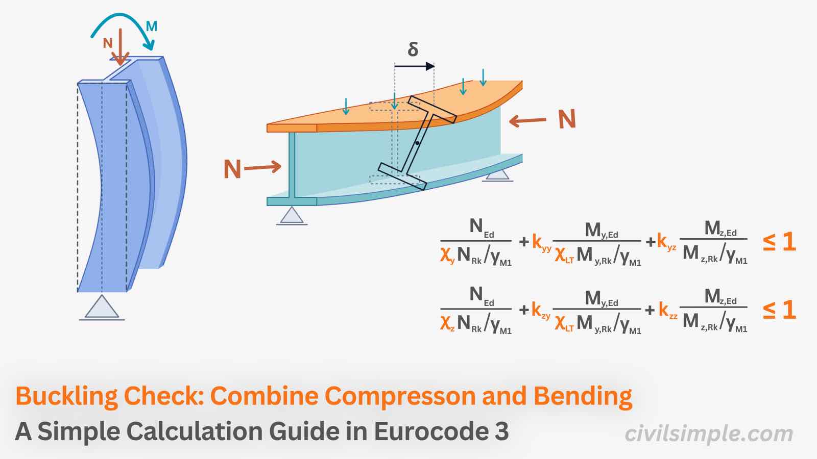
It is a stability check for members that carries axial compression and bending at the same time (a beam-column) and has no restraint along the length being checked, so it is free to buckle sideways (flexural buckling) about either axis and to twist (lateral-torsional buckling).
Why it is needed: Compression and bending interact and increase the risk of buckling. A bending moment causes the member to deflect, while compression acts on the deflected member and increases the bending effect. This is why combined compression and bending must be checked together.
💡 The idea behind the calculation
The combined check measures how much of the member's capacity is used by compression and bending about each axis.
Each effect is expressed as a utilisation ratio, including the effect of buckling. These ratios are then combined using interaction factors (k), which account for how compression and bending influence each other. The final combined utilisation should remain within 100%.
The two equations are Eq. 6.61 & 6.62,EN 1993-1-1:
The combine check depending on three componenets:
- Axial utilisation ( ): Flexural buckling factor χ Cl 6.3.1 and Compression Capacity NRk Cl 6.2.4
- Major-axis bending utilisation ( ): Lateral Torsional Buckling factor χLT Cl 6.3.2 and Bending Capacity MRk Cl 6.2.5
- Minor-axis utilisation ( ): Bending Capacity MRk Cl 6.2.5
kyy, kyz, kzy and kzz - Four interaction factors
The combined check uses four interaction factors kyy, kyz, kzy and kzz to account for how axial compression and bending interact. These factors captures several effects:
- Shape of the moment diagram: It represented by Cm (Cmy, Cmz, CmLT).
- Section class and shape: Based on class and shape of section, different formulas are used to obtain k factors
- Torsional behaviour: an open I-section can twist and buckle laterally, a hollow section hardly does. This decides which table of factors applies.
- Cross-coupling between axes: bending about one axis reduces the capacity about the other — represented by kyz and kzy.
Annex A vs. Annex B - obtaining interaction factors kyy, kyz, kzy and kzz
Eurocode 3 provides two approaches for obtaining the interaction factors. Annex A and Annex B use different formulae and calculation procedures, so they can give different levels of conservatism and require different amounts of calculation.
Comparsion of Annex A and Annex B
| Annex A (Method 1) | Annex B (Method 2) | |
|---|---|---|
| Approach | Derives each k from first principles: elastic critical forces, plastic modulus ratio, torsional constants and more | Ready-made formulae in three tables (B.1, B.2, B.3) |
| Effort | Long — many auxiliary parameters (μ, w, npl, aLT … plus Cyy etc.) | Short — hand-calculation friendly |
| Result | Usually less conservative, more economical | Slightly more conservative, easy to audit |
| Best for | Software, heavily loaded or optimised members | Hand checks, preliminary design, reports |
📖 Glossary: parameters in the combined check
As many parameters are involved in the calculation, the glossary below lists each one with a short explanation. The step-by-step calculation guide follows right after it.
Common Glossary for the Combined Compression and Bending Check
| Symbol | Name | Simple meaning |
|---|---|---|
| NEd | Design axial compression force | Factored axial load on the member |
| My,Ed, Mz,Ed | Design bending moments | Maximum factored moment about the major (y-y) and minor (z-z) axes between braced points |
| ΔMy,Ed, ΔMz,Ed | Moments from centroid shift | Only for Class 4: NEd × the shift of the effective centroid. Zero for Class 1–3 |
| NRk | Characteristic compression resistance | fy × A (Class 1–3) or fy × Aeff (Class 4) |
| My,Rk, Mz,Rk | Characteristic moment resistance | fy × Wpl (Class 1–2), fy × Wel (Class 3), fy × Weff (Class 4) |
| χy, χz | Flexural buckling reduction factors | From Cl. 6.3.1: fraction of NRk left after buckling about y-y or z-z |
| χLT | Lateral-torsional buckling reduction factor | From Cl. 6.3.2; take 1.0 if the member is not susceptible to torsional deformation |
| λ̄y, λ̄z | Non-dimensional slenderness | How slender the member is about each axis (from the flexural buckling check) |
| Ncr,y, Ncr,z | Elastic critical buckling force | Load at which a perfect member would buckle about each axis |
| γM1 | Partial safety factor | 1.0 as recommended — check your National Annex |
| kyy, kyz, kzy, kzz | Interaction factors | Cover second-order effects and the coupling between axes; found from Annex A or B |
| Cmy, Cmz, CmLT | Equivalent uniform moment factors | Turn the actual moment diagram into an equivalent uniform moment (1.0 = uniform moment, the worst case) |
| ψ | End moment ratio | Smaller end moment ÷ larger end moment, from −1 to 1 |
| αs, αh | Moment diagram ratios | Used in Table B.3 when lateral loads act between the supports |
| ny, nz | Axial utilisation | NEd / (χyNRk/γM1) and NEd / (χzNRk/γM1) — shorthand used in this guide |
| Wpl, Wel, Weff | Plastic, elastic, effective section modulus | Choice depends on section class |
| A, Aeff | Gross and effective area | Aeff for Class 4 |
| μ, w, npl, aLT, bLT … | Annex A auxiliary parameters | Only needed for Method 1 (Annex A); not used in Annex B |
📍 Quick Calculation Guideline for the Combined Check (Annex B)
Given a beam-column with NEd, My,Ed and Mz,Ed and no intermediate restraint, determine whether it passes Cl. 6.3.3
The steps below follow Annex B (Method 2). Use the first-order moments between braced points — where the frame is sensitive to sway, the second-order (P-Δ) effects belong to the frame analysis.
Collect the design forces and section data
Take NEd, My,Ed and Mz,Ed (first-order moments between braced points), the steel grade fy, and classify the section (Class 1–4).
Calculate the section resistances
NRk = fy · A (for a Class 4 section: fy · Aeff).
My,Rk and Mz,Rk = fy · Wpl (Classes 1–2), fy · Wel (Class 3) or fy · Weff (Class 4).
For Class 4, also find the centroid-shift moments ΔMy,Ed and ΔMz,Ed — they are zero for Classes 1–3.
Get the buckling reduction factors
χy and χz from the flexural buckling check (Cl. 6.3.1), run for each axis.
χLT from the lateral-torsional buckling check (Cl. 6.3.2)
where χLT = 1.0 if the member is not susceptible to torsional deformation (e.g. hollow section).
Choose the table for k interactive factors
Section that not susceptible to torsion → Table B.1.
Section that susceptible (typically an open I- or H-section without torsional restraint) → Table B.2.
Find Cmy, Cmz and CmLT from Table B.3
The factors depend on the moment diagram between braced points — pick from the reference table below.
Use Cm = 1.0 for a sway buckling mode, and remember Cm = 1.0 is always a safe, conservative choice.
| Moment diagram between braced points | Cm (Cmy, Cmz, CmLT) |
|---|---|
| Uniform moment (ψ = 1.0, the worst case) | 1.0 |
| Linear diagram from end moments, ratio ψ (−1 ≤ ψ ≤ 1) | 0.6 + 0.4·ψ, but not less than 0.4 |
| Simply supported, uniform lateral load, no end moments | 0.95 |
| Simply supported, point load at mid-span, no end moments | 0.90 |
| End moments combined with lateral load | Use Table B.3 of EN 1993-1-1 directly (depends on αs or αh) |
Calculate the interaction factors kyy, kyz, kzy and kzz
Work with the shorthand axial utilisations: ny = NEd / (χyNRk/γM1) and nz = NEd / (χzNRk/γM1).
Pick each factor from the tables below — depending on the section class and on the table chosen in Step 4 (Table B.1/B.2).
| Factor | Class 1 and 2 | Class 3 and 4 |
|---|---|---|
| kyy | Cmy [ 1 + (λ̄y − 0.2)·ny ] ≤ Cmy (1 + 0.8·ny) | Cmy [ 1 + 0.6·λ̄y·ny ] ≤ Cmy (1 + 0.6·ny) |
| kzz — I- and H-sections | Cmz [ 1 + (2·λ̄z − 0.6)·nz ] ≤ Cmz (1 + 1.4·nz) | Cmz [ 1 + 0.6·λ̄z·nz ] ≤ Cmz (1 + 0.6·nz) |
| kzz — rectangular hollow sections | Cmz [ 1 + (λ̄z − 0.2)·nz ] ≤ Cmz (1 + 0.8·nz) | Cmz [ 1 + 0.6·λ̄z·nz ] ≤ Cmz (1 + 0.6·nz) |
| kyz | 0.6·kzz | kzz |
| kzy — not susceptible to torsion (Table B.1) | 0.6·kyy | 0.8·kyy |
For kzy when the member is susceptible to torsional deformation (Table B.2):
| Section class | kzy |
|---|---|
| Class 1 and 2 & λ̄z ≥ 0.4 | 1 − [ 0.1·λ̄z / (CmLT − 0.25) ]·nz, but not less than 1 − [ 0.1 / (CmLT − 0.25) ]·nz |
| Class 1 and 2 & λ̄z < 0.4 | 0.6 + λ̄z, but not more than 1 − [ 0.1·λ̄z / (CmLT − 0.25) ]·nz |
| Class 3 and 4 | 1 − [ 0.05·λ̄z / (CmLT − 0.25) ]·nz, but not less than 1 − [ 0.05 / (CmLT − 0.25) ]·nz |
For I- and H-sections and rectangular hollow sections with compression and major-axis bending only (Mz,Ed = 0), kzy = 0 may be taken.
Calculate based on Eq. 6.61 and Eq. 6.62 and check
Eq. 6.61: NEd / (χy·NRk/γM1) + kyy·(My,Ed + ΔMy,Ed) / (χLT·My,Rk/γM1) + kyz·(Mz,Ed + ΔMz,Ed) / (Mz,Rk/γM1) ≤ 1.0
Eq. 6.62: NEd / (χz·NRk/γM1) + kzy·(My,Ed + ΔMy,Ed) / (χLT·My,Rk/γM1) + kzz·(Mz,Ed + ΔMz,Ed) / (Mz,Rk/γM1) ≤ 1.0
Evaluate Eq. 6.61 and Eq. 6.62. check if both are ≤ 1.0.
⚠️ Common mistakes to avoid
- Checking compression and bending separately and adding the ratios — the second-order amplification between them is exactly what the interaction equations capture
- Taking χLT = 1.0 for an open I-section that can twist — it is only valid when the section is not susceptible to torsional deformation
- Picking the wrong table in Step 4 — the two tables differ only in kzy, but that factor matters
- Forgetting the ΔM terms for a Class 4 section, or using Wpl where Weff is required
- Feeding second-order moments into the check — Annex B expects first-order moments between braced points; sway effects belong to the frame analysis
- Checking the whole member instead of each segment between restraints, with its own moment diagram and buckling length
- Forgetting the γM1 value and the method choice of your National Annex
🙋 Frequently asked questions
1. What is the combined compression and bending check in Eurocode 3?
It is the stability check for a beam-column — a member under axial compression and bending at the same time. Eurocode 3 checks it with the two interaction equations (Cl. 6.3.3, Eq. 6.61 and 6.62), and Annex B provides simple formulae for the interaction factors in them.
2. Why can't I check N and M separately and add the utilisation ratios?
Because compression and bending make each other worse: the bending bows the member, and the compression acts on that bow, producing additional second-order moment. The interaction equations capture this amplification through the interaction factors k — adding two separate ratios would miss it.
3. What is a beam-column?
A member that carries axial compression and bending simultaneously. Nearly every real frame column is one: wind, eccentric load paths and frame action always introduce some moments on top of the axial force.
4. When can χLT be taken as 1.0 in the combined check?
When the member is not susceptible to torsional deformation — for example hollow sections, or a section restrained against twisting. Otherwise χLT comes from the lateral-torsional buckling check of Cl. 6.3.2.
5. What is the difference between Annex A and Annex B?
Both provide the interaction factors k. Annex A (Method 1) derives each factor from first principles — usually less conservative and suited to software. Annex B (Method 2) provides ready-made formulae in Tables B.1–B.3 — slightly more conservative but hand-calculation friendly. Each country's National Annex decides which method(s) are allowed.
6. What are the ΔM terms in the interaction equations?
They are additional moments caused by the shift of the centroid of the effective cross-section, and apply only to Class 4 sections (ΔM = NEd × the centroid shift). For Class 1–3 sections the ΔM terms are zero.
📋 Key takeaways
- The combined check (Cl. 6.3.3) is the stability check for beam-columns — members under axial compression and bending at the same time.
- It uses two interaction equations: Eq. 6.61 (major axis y-y) and Eq. 6.62 (minor axis z-z) — both must be ≤ 1.0.
- Each equation adds three utilisations: axial (with χ), major-axis bending (with χLT) and minor-axis bending — tied together by the interaction factors k.
- Annex B (Method 2) gives the hand-friendly k factors: choose Table B.1 or B.2 by torsional susceptibility (they differ only in kzy), and Cm from Table B.3.
- Check each segment between restraints on its own, with first-order moments and the buckling length of that segment.
📄 Need a beam-column check in your design report?
The combined check usually decides which capacity of a real frame column you are allowed to use. If you want a ready-to-submit design report with the combined compression and bending check, the buckling checks, section classification and the full cross-section check in Eurocode 3, feel free to try our application — what you need is just the design data values, and a ready-to-submit PDF report will be generated in a minute.
References
- Eurocode 3: Design of steel structures — Part 1-1: General rules and rules for buildings (EN 1993-1-1) — ·2005

CivilSimple Team
The CivilSimple Team writes practical engineering guides for the profession and the curious. All articles are reviewed for technical accuracy before publication.