👋 Introduction
Steel beams carry bending, but an unrestrained beam can fail in a way the cross-section check never sees: the compression flange moves sideways and the section twists long before the steel yields.
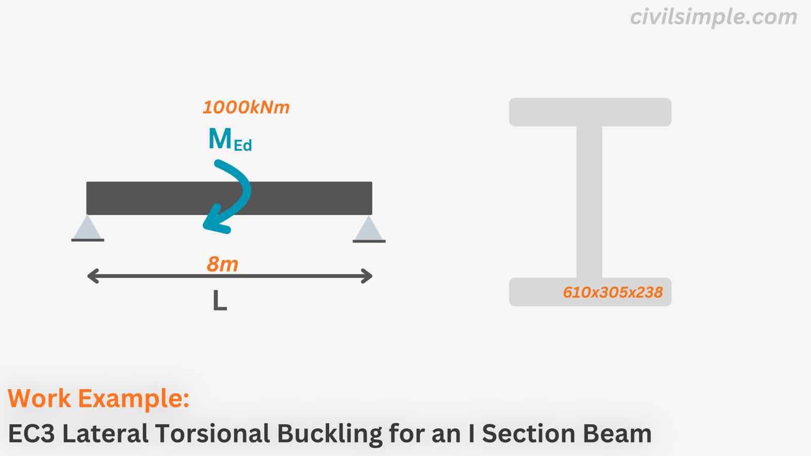
This work example runs the lateral-torsional buckling check of a hot-rolled I-section 610x305x238 UB in S355 carrying a design bending moment MEd = 1,000 kNm about the major axis over a laterally unrestrained length of 8.0 m, in the same order a calculation report runs it:
- Classify the section — the class decides which modulus the bending resistance is built from
- Cross-section bending check Mc,y,Rd
- LTB check Mb,Rd — elastic critical moment Mcr, slenderness λ̄LT, buckling curve and the reduction factor χLT, with the buckling resistance governing
The concept behind each step is explained step by step in the companion article: Lateral Torsional Buckling in Eurocode 3 - A Simple Calculation Guide for Beams.
📐 Design Data
Below is the design information of the I-section (610x305x238), which we will check under major-axis bending and lateral-torsional buckling.
| Steel Section | ||
|---|---|---|
| Type | I-section | |
| Standard | 610x305x238 | |
| Depth, h | 635.8mm | |
| Breadth, b | 311.4mm | |
| Flange Thickness, tf | 31.4mm | |
| Web Thickness, tw | 18.4mm | |
| Root Radius, r | 16.5mm |
| Material | ||
|---|---|---|
| Steel Grade | S355 | |
| Yield Strength, fy | 355 N/mm² | |
| Young's Modulus, E | 210,000 N/mm² | |
| Shear Modulus, G | 81,000 N/mm² | |
| Partial Factor, γM0 | 1.0 | |
| Partial Factor, γM1 | 1.0 |
| Design Actions and Restraints | ||
|---|---|---|
| Design Bending Moment (Major Axis y), MEd | 1,000 kNm | |
| Unrestrained Length between Lateral Restraints, Lcr | 8.0 m |
🔢 Calculation Steps
1.Section Properties of I section (610x305x238)
| Area | = | |
| Moment of Inertia, Major | = | |
| Moment of Inertia, Minor | = | |
| Elastic Modulus, Major | = | |
| Plastic Modulus, Major | = | |
| Warping Constant | = | |
| Torsional Constant | = |
2.Section Classification Table 5.2
| Material Factor | = | |
| Outstand Flange | = | |
| Part Subject to Compression | ||
| Web, subject to Compression | = | |
| Part Subject to Bending | ||
| Web, subject to Bending | = | |
| The overall cross-section is: | ||
| - Class 2 subjected to Compression | ||
| - Class 1 subjected to Bending | ||
3.Section Check with Design Action
3.1Bending check - Class 1 section Cl.6.2.5
| Design Resistance for Bending at y(Cl. 6.2.5(2), Eq. 6.13) ⓘ | ||
|---|---|---|
| = | ||
| = | ||
| = | ||
| Bending Check at major axis(Cl. 6.2.5, Eq. 6.12) | ||
|---|---|---|
| = | ||
| = | ||
| = | ||
∴ The section is sufficient for Pure Bending
3.2Lateral-torsional buckling check Cl.6.3.2
Following the check order of the LTB guide: Mcr → λLT → buckling curve → χLT → Mb,Rd.
| According to Cl. 6.3.2.3: | ||
| Plateau slenderness | = | |
| Curve shape factor | = | |
| Curve shape factor | = | |
| For Calculation of Mcr: | ||
| Moment diagram factor | = | |
3.2.1Elastic critical moment Mcr
| Elastic Critical Moment for Lateral-Torsional Buckling(NCCI SN003) | ||
|---|---|---|
| = | ||
| = | ||
| = | ||
| where | ||
| Lateral Euler term | = | |
| Torsional term | = | |
3.2.2Non-dimensional slenderness λ̄LT Cl.6.3.2.2
| Slenderness, Lateral-Torsional(Cl. 6.3.2.2(1), Eq. 6.56 definition) | ||
|---|---|---|
| = | ||
| = | ||
| = | ||
3.2.3Buckling curve Table 6.5
| For this hot-rolled I-section, the special method selects: | ||
| = | ||
| From Table 6.5 gives: | ||
| - buckling curve c, with imperfection factor αLT = 0.49 from Table 6.3 | ||
3.2.4Reduction factors ΦLT and χLT Cl.6.3.2.3
| Intermediate Factor, lateral-torsional(Cl. 6.3.2.3(1)) | ||
|---|---|---|
| = | ||
| = | ||
| = | ||
| Reduction Factor, lateral-torsional(Cl. 6.3.2.3(1), Eq. 6.57) | ||
|---|---|---|
| = | ||
| = | ||
| = | ||
3.2.5Moment distribution factor f and χLT,mod Cl.6.3.2.3
The moment shape also enters through the factor f, with the correction factor kc from Table 6.6 (kc = 1.0 for a uniform moment, ψ = 1):
| Modification Factor for moment distribution(Cl. 6.3.2.3(2)) | ||
|---|---|---|
| = | ||
| = | ||
| = | ||
| Reduction Factor with moment distribution considered(Cl. 6.3.2.3(2), Eq. 6.58) | ||
|---|---|---|
| = | ||
| = | ||
| = | ||
3.2.6Design buckling resistance moment and the check Cl.6.3.2.1
| Design Buckling Resistance Moment(Eq. 6.55) | ||
|---|---|---|
| = | ||
| = | ||
| = | ||
| Buckling Check under bending(Cl. 6.3.2.1(1), Eq. 6.54) | ||
|---|---|---|
| = | ||
| = | ||
| = | ||
∴ The section is sufficient for Lateral-Torsional Buckling — the buckling check governs.
📋 Summary
| The I Section (610x305x238) is sufficient under Moment at Major Axis (1,000 kNm), it : | ||
| ✓ Bending Check at major axis (util: 38%) | ||
| ✓ Lateral-Torsional Buckling Check (util: 62%) - governing |
| Quantity | Cross-section bending (Cl. 6.2.5) | Lateral-torsional buckling (Cl. 6.3.2) |
|---|---|---|
| Slenderness | — | λ̄LT = 1.06 |
| Buckling curve (αLT) | — | c (0.49) |
| Resistance | Mc,y,Rd = 2 658 kNm | Mb,Rd ≈ 1 621 kNm |
| Utilisation | 0.38 | 0.62 — governing |
🔧 Improvement of Lateral Torsional Buckling Capacity
If the compression flange were restrained at mid-span:
-
Lcr would halve to 4.0 m, Mcr would rise from 2 381 kNm to about 7 180 kNm,
-
λ̄LT would fall to 0.61 and χLT would rise to about 0.88, taking the utilisation down from 62% to roughly 43%.
∴ Adding lateral restraints is the most effective fix for LTB.
🙋 Frequently asked questions
1. What is lateral torsional buckling in an I-section beam?
When a slender beam bends about its major axis, the compression flange behaves like a slender column: it cannot bow in the plane of the web, so it moves sideways — and because the tension flange resists that movement, the whole section twists. The beam can therefore fail well below its cross-section capacity (2 658 kNm here). The guide article explains the mechanism with diagrams.
2. Which Eurocode 3 clause covers the LTB check?
Cl. 6.3.2 of EN 1993-1-1. It offers the general case (Cl. 6.3.2.2) and the special method for rolled or equivalent welded sections (Cl. 6.3.2.3), which has a longer plateau (λ̄LT,0 = 0.4), a flatter curve (β = 0.75) and the optional factor f. This example uses the special method, as most tools do for rolled beams — the National Annex may restrict the choice.
3. What is the elastic critical moment Mcr?
The theoretical moment at which a perfect, elastic beam would buckle sideways — the beam version of the Euler critical load. It collects the sideways bending stiffness (π²EIz/L²) and the torsional stiffness (G·It, Iw), modified by the moment shape through C₁. Eurocode 3 does not give the formula — it comes from guidance such as NCCI SN003 or from structural software.
4. When can lateral torsional buckling be ignored?
When the compression flange is fully restrained and twist is prevented (e.g. by a concrete slab or closely spaced bracing), for sections not susceptible to LTB such as CHS/SHS, and when the beam is stocky enough: λ̄LT ≤ 0.4 or MEd/Mcr ≤ 0.16 (Cl. 6.3.2.2(4) with the recommended values). Here λ̄LT = 1.06, so the full check is required.
5. How does the bending moment diagram affect the result?
A uniform moment is the worst case: it gives C₁ = 1.0 and kc = 1.0. A varying diagram (≈ 1.13 for a UDL, ≈ 1.35 for a central point load) gives a higher Mcr and, in the special method, a moment-gradient benefit through the factor f. Keep C₁ and kc consistent — both describe the same moment diagram.
6. Does the position of the load matter?
Yes. A load applied on the top flange is destabilising and lowers Mcr, while a load on the bottom flange is stabilising. The simplified Mcr formula used here assumes loading at the shear centre; for top-flange loading use the full expression from NCCI SN003 or structural software.
📄 Need a Beam Lateral Torsional Buckling Check in Your Design Report?
If you want a ready-to-submit design report with the lateral-torsional buckling check, section classification and the full cross-section check in Eurocode 3, feel free to try our application — what you need is just the design data values, and a ready-to-submit PDF report will be generated in a minute.
References
- Eurocode 3: Design of steel structures — Part 1-1: General rules and rules for buildings (EN 1993-1-1) — ·2005
- NCCI: Elastic critical moment for lateral torsional buckling (SN003) —

CivilSimple Team
The CivilSimple Team writes practical engineering guides for the profession and the curious. All articles are reviewed for technical accuracy before publication.