👋 Introduction
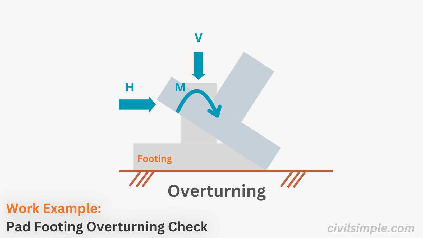
A pad footing must be checked against overturning to ensure its stability:
- Overturning forces: Horizontal forces and applied moments tend to rotate the footing about its toe (the edge of the footing base).
- Resisting forces: The vertical load from the structure and the footing’s own weight help resist overturning by providing a stabilising moment.
Below work example runs the overturning check of a 3.0 m × 3.0 m pad footing, 0.5 m deep, carrying a horizontal force Fy = 50 + 10 kN, an applied moment My = 50 + 50 kNm and a vertical force Fx = 20 + 5 kN, in the same order a calculation report runs it:
- Self weight — the weight that creates the restoring moment
- Restoring moment — the vertical forces about the toe
- Overturning moment — the applied moment and the horizontal force
- Overturning check — restoring against overturning, with the required factor of safety
The concept behind each step is explained in the companion article: Pad Footing Stability Check: Sliding, Overturning and Bearing Capacity - A Simple Guide.
📐 Design Data
Below is the design information of the pad footing, which we will check under the horizontal force and the applied moment.
| Pad Footing | ||
|---|---|---|
| Type | Pad footing (concrete) | |
| Length, L | 3.0 m | |
| Width, W | 3.0 m | |
| Depth, D | 0.5 m |
| Design Loads | ||
|---|---|---|
| Vertical Force, Fx (Dead / Live) | 20 kN / 5 kN | |
| Horizontal Force, Fy (Dead / Live) | 50 kN / 10 kN | |
| Applied Moment, My (Dead / Live) | 50 kNm / 50 kNm |
| Safety Factor | ||
|---|---|---|
| Factor of Safety, Overturning | 1.5 |
| Load Combination (SLS) | ||
|---|---|---|
| Dead Load Factor, fDL | 1.0 | |
| Live Load Factor, fLL | 1.0 |
🔢 Calculation Steps
1.Footing Self Weight
| Footing Volume(Geometry) | ||
|---|---|---|
| = | ||
| = | ||
| = | ||
| Footing Self Weight(Concrete density ρ = 25 kN/m³) | ||
|---|---|---|
| = | ||
| = | ||
| = | ||
2.Restoring Moment about the Toe
| Vertical Force (service)(SLS load combination) | ||
|---|---|---|
| = | ||
| = | ||
| = | ||
| Resistance Moment about the Toe(Restoring moment) | ||
|---|---|---|
| = | ||
| = | ||
| = | ||
3.Overturning Moment about the Toe
| Horizontal Force (service)(SLS load combination) | ||
|---|---|---|
| = | ||
| = | ||
| = | ||
| Applied Moment (service)(SLS load combination) | ||
|---|---|---|
| = | ||
| = | ||
| = | ||
| Overturning Moment about the Toe(Overturning moment) | ||
|---|---|---|
| = | ||
| = | ||
| = | ||
4.Overturning Check
| Overturning Check(Factor of safety) | ||
|---|---|---|
| = | ||
| = | ||
| = | ||
∴ The section is sufficient for Overturning.
🙋 Frequently asked questions
1. What is the overturning check of a pad footing?
It confirms that the restoring moment of the vertical forces about the toe beats the overturning moment of the horizontal force and any applied moment, with a required factor of safety — here 206 kNm against 130 kNm, a factor of 1.59 against 1.5.
2. Why are the moments taken about the toe?
Because the toe — the leading edge of the base (point A in the figure) — is the edge the footing would rotate about if it tipped. Taking moments about any other point would mix in forces that do not actually resist the rotation.
3. Why are service (unfactored) loads used?
Like the sliding check, overturning is a stability check that many design codes evaluate at the service level with a factor of safety on the result — the SLS combination (f = 1.0) is used here, as in the source calculation. Check which combination your design code requires.
4. What can I do if the overturning check fails?
Widen the base — it increases the lever arm W/2 and the self weight together. Adding weight on the footing also helps. Note that deepening the footing is less effective for overturning, because the horizontal force acts at the top — a deeper footing raises that force's lever arm as well.
5. What is the difference between overturning and sliding?
Overturning is a rotation about the toe — a moment check. Sliding is a rigid sideways movement — a force check. A footing that passes one can still fail the other; the sliding work example shows the force check, and the stability check guide runs all three checks together.
📄 Need a Pad Footing Overturning Check in Your Design Report?
If you want a ready-to-submit design report with the overturning check and the full stability checks of your pad footing, feel free to try our application — what you need is just the design data values, and a ready-to-submit PDF report will be generated in a minute.

CivilSimple Team
The CivilSimple Team writes practical engineering guides for the profession and the curious. All articles are reviewed for technical accuracy before publication.